Surface-mounted collision sensor, and method for collision detection

a collision sensor and surface-mounted technology, applied in the direction of instruments, fluid pressure measurement, radiation safety means, etc., can solve the problems of affecting the safety of the environment, and the inability to install protective devices,

Active Publication Date: 2017-06-27
SIEMENS HEALTHCARE GMBH
View PDF8 Cites 0 Cited by
  • Summary
  • Abstract
  • Description
  • Claims
  • Application Information

AI Technical Summary

Benefits of technology

[0021]An object of the present invention is to provide a sensor technology for collision-detection for use in environments of the type described above, wherein the disadvantages of the aforementioned known technologies are avoided or minimized.
[0022]This object is achieved in accordance with the present invention by an apparatus assembly that is part of a medical apparatus and that is mounted for movement in a medical examination environment in a manner that exposes persons or objects in the vicinity of the movement of the apparatus assembly to the risk of injury due to a collision with the apparatus assembly, wherein a surface of the apparatus assembly is covered, substantially completely, by a PVDF cover assembly that includes a PVDF foil with a conductive layer disposed on opposite sides of the PVDF foil. The apparatus assembly according to the invention is based on the insight that the piezoelectric property of PVDF can be exploited for use as a collision-detection sensor, when a PVDF cover assembly of this type is appropriately attached to the surface of the apparatus assembly, and is protected from damage by an exterior coating.
[0026]In a further embodiment, two such PVDF cover assemblies can be situated one above the other between the resilient material that is on the surface of the component, and the exterior protective coating. The use of two such PVDF cover assemblies provides redundancy in detecting collisions, as well as providing a higher likelihood that even if one of the PVDF cover assemblies is damaged, the other will still remain functional.

Problems solved by technology

There is also a risk that the moving component may collide with an object within its movement range, thereby damaging the component or the object, or both.
In workspaces of the type described above, it is generally not possible to install protective devices that would physically separate humans in the environment from a collision with a component moved by the robot.
Since contact between personnel / objects and moving objects can occur anywhere in an operating room environment and at any time, a risk of collision remains, despite the use of known collision-detection techniques.
This requires a sensor technology that is “surface-covering,” meaning that sensing capability is provided over the entire surface of any component or assembly that presents a risk of injury due to a collision.
A disadvantage that all of these known approaches have in common is that they are difficult to integrate into the covering of a surface, particularly complexly-shaped surfaces of parts of a medical apparatus, in a cost-effective manner, while still maintaining reliable collision detection.
For example, the aforementioned pressure-sensitive bumpers, which emit an electrical signal when strongly deformed, can be used individually and locally only to a limited extent, due to the geometry of such bumpers.
Impact angles that are greater than 45° can lead to an erroneous response.
Moreover, such bumpers usually are not able to detect collisions that occur within a few millimeters from the edges of the bumper.
The lacquered foam coating is very expensive, and is subject to being damaged by sharp articles.
This means that such parts can have only a predetermined maximum weight, otherwise the restoring force on the housing thereof would be too large in order to trigger a detection in the event of a collision.
Because collision with such a housing can occur from many different directions, detection must be ensured in all directions, and this can be realized only by using a very complex and mechanically delicate and expensive configuration.
Moreover, separation lines, such as produced by edges and grooves, must be provided in order to achieve this movement detection, and sterilization and hygienic problems can result from the presence of such crevices in a medical environment.
Known problems associated with PVDF membranes designs are the implementation of large-area elements, applications with large force impacts, and exposure to sharp articles.

Method used


Image

  • Surface-mounted collision sensor, and method for collision detection
  • Surface-mounted collision sensor, and method for collision detection
  • Surface-mounted collision sensor, and method for collision detection

Examples


Embodiment Construction

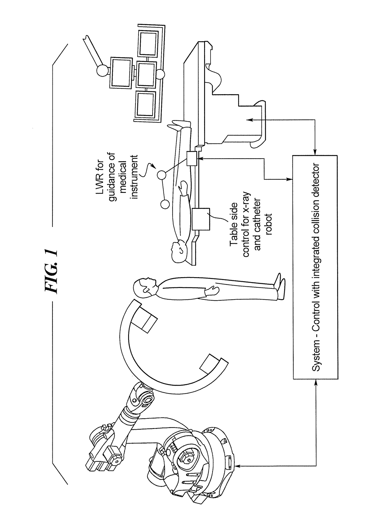
[0035]FIG. 1 schematically illustrates an environment in which the collision sensor in accordance with the present invention is suitable for use. In the example shown in FIG. 1, this environment is a medical examination or operating room in which a robotically-operated x-ray imaging system, shown at the left in FIG. 1, is moved relative to an attendant or a physician (shown standing in the center of FIG. 1) so as to obtain medical images of a patient lying on a patient table. The examination may include the use of a lightweight robot LWR, for guidance of a medical instrument. Display screens are shown at the right in FIG. 1, and the patient table, as is known, has a side control for the x-ray imaging system and for the catheter robot. All components are operated by a system control, which has an integrated collision detector. The collision detector is explained in further detail below, and provides electrical signals indicating the occurrence of a collision between any of the compon...


PUM

PropertyMeasurementUnit
thicknessaaaaaaaaaa
resilientaaaaaaaaaa
conductiveaaaaaaaaaa

Abstract

An apparatus assembly of a medical apparatus is equipped for collision detection by attaching a polyvinylidene fluoride (PVDF) cover assembly to at least one rigid surface of the apparatus assembly, with a resilient material between the PVDF cover assembly and the rigid surface. The PVDF assembly is composed of a PVDF foil with electrically conductive layers on opposite sides thereof. A protective layer covers the PVDF cover assembly. Electrical leads are connected to the conductive layers, and the piezoelectric property of the PVDF foil produces a voltage across the leads when a force associated with a collision acts on the PVDF foil. A detection circuit detects this voltage and initiates an appropriate response to the collision.

Description

RELATED APPLICATION[0001]The present application claims the benefit of the filing date of provisional application 61 / 902,471, filed on Nov. 11, 2013, the content of which is incorporated herein by reference.BACKGROUND OF THE INVENTION[0002]Field of the Invention[0003]The present invention concerns devices and techniques for avoiding collisions in the environment of a system having a heavy, movable component, and personnel and / or objects that are present in the environment of the system while that component may be moving. In particular; the present invention concerns avoiding such collisions between persons, including operating personnel and patients, as well as other objects that are present in an examination room in which a medical examination or procedure is being implemented using a medical apparatus that has at least one such heavy, movable component, such as a robotically-operated x-ray imaging system.[0004]Description of the Prior Art[0005]Medical diagnosis and intervention sy...

Claims


Application Information

Patent Timeline
Patent Type & Authority Patents(United States)
IPC IPC(8): G01L1/16H01L41/113A61B6/10G01L9/00A61B6/00H01L41/193
CPCH01L41/1132A61B6/102A61B6/4441G01L9/008H01L41/193H10N30/302H10N30/857
Inventor SATTLER, STEFANSCHUSTER, STEFAN
Owner SIEMENS HEALTHCARE GMBH
Why Eureka
Try Eureka