Motor protection device

a protection device and motor technology, applied in the direction of electric motor control, electrical apparatus, control system, etc., can solve the problems of not providing an optimized criterion for the recovery of the motor, the temperature may only reflect the overload condition in a delayed and slow manner, and the first-mentioned drawback is also presen

Pending Publication Date:
View PDF0 Cites 0 Cited by
  • Summary
  • Abstract
  • Description
  • Claims
  • Application Information

AI Technical Summary

Problems solved by technology

This approach, however, has the disadvantage that an overload condition may be reflected by the temperature only in delayed and slow manner.
Further, it necessarily requires temperature sensors as additional components and additional wiring for the connection.
At least the first-mentioned drawback is also present if the motor temperature is measured indirectly via the coil resistance.
This approach, however, has the general disadvantage that the current provides a criterion for switching off the motor in case of an overload conditions, but does not provide an optimized criterion for a recovery of the motor from the overload condition, i. e. when the motor may again be safely energized.
Such recovery time, however, may be too short under certain conditions and / or be unnecessarily long under other conditions.
This approach, however, is only suited for detecting a blocked drive, but not for reliably detecting an overload when the motor is still running.

Method used


Image

  • Motor protection device
  • Motor protection device
  • Motor protection device

Examples


Embodiment Construction

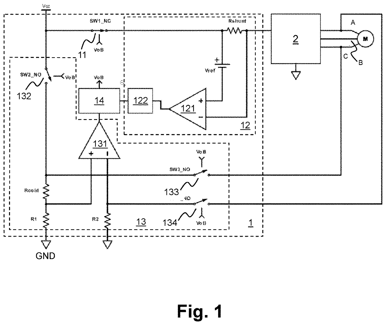
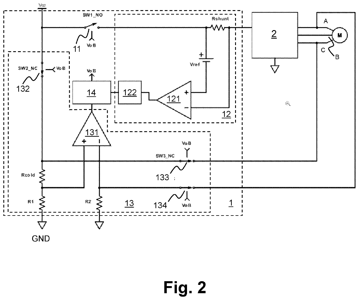
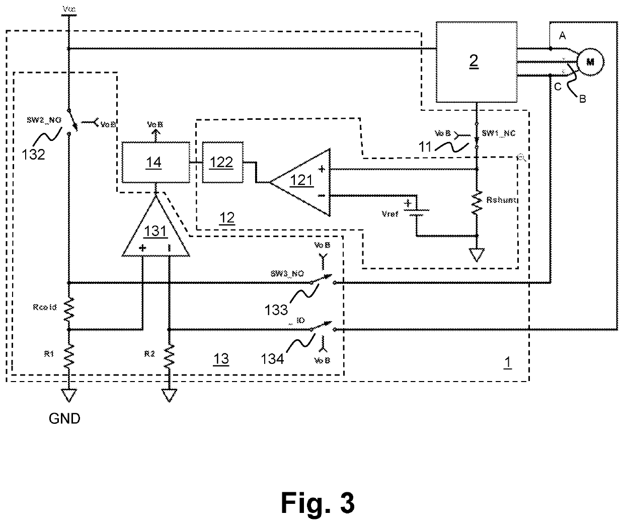
[0049]In the following, reference is first made to FIG. 1 and FIG. 2. FIG. 1 and FIG. 2 show a first embodiment of a motor protection device 1 in an operational configuration together with a power supply, a power module 2 and an electric motor M as schematic circuit diagram. FIG. 1 shows the operation mode and FIG. 2 shows the overload mode. The electric motor M, the power module 2 and the overload detection circuit 12 form, in combination, an electric drive that is powered via the power supply.

[0050]The power supply is exemplarily assumed as constant voltage DC power supply with supply voltage Vcc. It is noted that throughout this document a voltage is generally assumed as measured against ground (GND) potential.

[0051]The motor M is exemplarily assumed as electronically commutated motor. The drive circuit 2 is designed as generally known in the art. It generates at its output side the drive signals for the three motor phases respectively the three motor coils (not individually show...


PUM


Abstract

Disclosed is a motor protection device (1). The motor protection device (1) includes an interrupter unit (11, Q1, Q2) for electrically connecting a power supply (Vcc) and an electric motor (M) in an operation mode and electrically disconnecting the power supply (Vcc) and the electric motor in an alternative overload mode. The motor protection device further includes an overload detection unit (12). The overload detection unit (12) is configured to monitor a motor current and to control the interrupter unit (11, Q1, Q2) to switch from the operation mode into the overload mode if the motor current indicates an overload condition of the electric motor (M) in the operation mode. The motor protection device (1) further includes a recovery detection unit (13). The recovery detection unit (13) is configured to monitor a motor temperature and to control the interrupter unit (11, Q1, Q2) to switch from the overload mode back into the operation mode if the motor temperature indicates a recovery from the overload condition.

Description

FIELD OF THE INVENTION[0001]The present invention relates to protection devices for electric motors, electric drives with an electric motor and a protection device, as well as to methods for operating an electric motor. The invention is particularly useful in critical application where any damage of an electric drive and / or equipment that is actuated by an electric drive must be prevented with a high degree of safety.BACKGROUND OF THE INVENTION[0002]Electric motors and drives are used in a wide variety of applications, including safety-critical applications. Examples are critical safety valves operated by a servo drive, or safety drives e. g. in form of spring return drives that are used to move fire dampers or smoke dampers as used in fire protection systems.[0003]A general issue of concern for electric drives is the occurrence of overload conditions that may, if not detected and handled appropriately, at least significantly reduce the lifetime of the motor or further components, a...

Claims


Application Information

Patent Timeline
Patent Type & Authority Applications(United States)
IPC IPC(8): H02H7/085
CPCH02H7/0852H02H7/085H02H7/0833H02H3/093H02H3/066H02P29/027
Inventor GAETA, MAURIZIOGAY, THOMASHAAG, STEPHAN
Why Eureka
Try Eureka