Harmonics Measurement in Power Grids

a power grid and harmonic technology, applied in the direction of frequency selective voltage/current level measurement, measurement using digital techniques, instruments, etc., can solve the problems of inability to accurately measure voltages with frequencies higher than 50 hz, inability to accurately measure voltages, and high cost of inductive voltage transformers, especially those already installed, so as to achieve cost-effective and accurate measurement of harmonics, avoid or minimize disadvantages

Inactive Publication Date: 2021-01-14
INNOGY SE
View PDF0 Cites 0 Cited by
  • Summary
  • Abstract
  • Description
  • Claims
  • Application Information

AI Technical Summary

Benefits of technology

[0008]Based on this background, it is desirable to provide a solution that avoids or minimizes the disadvantages described above and, in particular, allows for a cost-effective and accurate measurement of harmonics in power grids even at frequencies higher than 50 Hz.

Problems solved by technology

However, they are usually unable to measure voltages with frequencies higher than 50 Hz accurately, as the transfer function of inductive voltage transformers is not known.
Measuring inductive voltage transformers, especially those already installed, is very costly and therefore unusual.
Voltage transformers that measure correctly over the frequency range of interest from 50 Hz to 10 kHz are considerably more expensive than conventional inductive voltage transformers.
At frequencies not equal to 50 Hz (e.g. in WTGs), especially above 1000 Hz, an accurate harmonic measurement cannot be guaranteed.

Method used


Image

  • Harmonics Measurement in Power Grids
  • Harmonics Measurement in Power Grids
  • Harmonics Measurement in Power Grids

Examples


Embodiment Construction

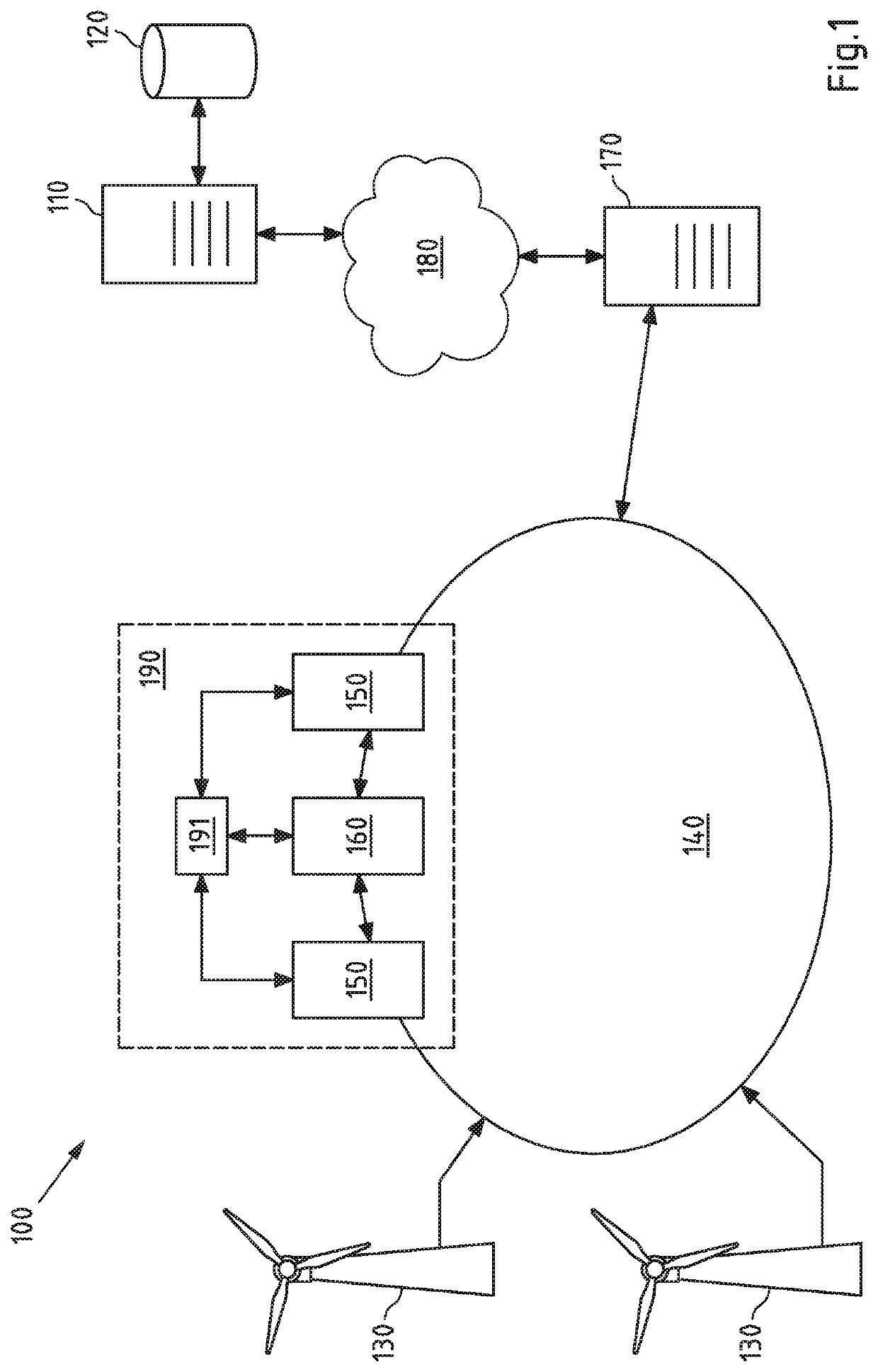
[0078]FIG. 1 shows an exemplary system 100 of an example embodiment according to the fourth aspect of the present invention. The system 100 comprises in the present case two of first voltage transformers 150, a second voltage transformer 160, a grid unit 191 comprised by a voltage measuring point 190, a server 170 which, for example, executes and / or controls a network control system and / or executes and / or controls a simulation software, a server 110 which, for example, performs and / or controls the present method according to the first aspect of the present invention, an optional database 120, in the present case two WTGs 130 which feed electrical energy into the power grid 140, and a communication network 180 (e.g. the Internet), via which at least server 170 can communicate with server 110. Alternatively, server 170 and server 110 can be directly connected to each other and communicate, for example, via a wired communication connection (e.g. according to the Local Area Network (LAN...


PUM


Abstract

The subject-matter relates to a method, performed by at least one apparatus, including: determining of a correction factor for at least one first voltage transformer arranged in a power grid, the correction factor being indicative of a correction for obtaining correct measured values measured by the at least one first voltage transformer, wherein the determining of the correction factor of the at least one first voltage transformer being performed at least partially based on a first measured voltage of the at least one first voltage transformer and a second measured voltage of the at least one first voltage transformer, wherein the second voltage of the at least one first voltage transformer is determined at least partially based on a known transfer function of at least one second voltage transformer and the first voltage of the at least one first voltage transformer is determined without taking into account the known transfer function of the at least one second voltage transformer; determining a calibration factor for the at least one first voltage transformer based at least in part on the determined correction factor; and outputting or causing the output of the determined calibration factor. The subject matter further relates to a correspondingly configured apparatus and a system.

Description

CROSS-REFERENCE TO RELATED APPLICATIONS[0001]This application is the United States national phase of International Application No. PCT / EP2019 / 054043 filed Feb. 19, 2019, and claims priority to German Patent Application No. 10 2018 106 200.1 filed Mar. 16, 2018, the disclosures of which are hereby incorporated by reference in their entirety.BACKGROUND OF THE INVENTIONField of the Invention[0002]The present subject-matter relates to a method, an apparatus and a system for optimised measurement of harmonics in power grids, in particular offshore and / or onshore grids, which are subject to harmonic loading, e.g. by a feed-in of electrical energy from wind turbine generators (WTG).Description of Related Art[0003]Inductive voltage transformers are very inexpensive and therefore widely used. However, they are usually unable to measure voltages with frequencies higher than 50 Hz accurately, as the transfer function of inductive voltage transformers is not known. Measuring inductive voltage t...

Claims


Application Information

Patent Timeline
Patent Type & Authority Applications(United States)
IPC IPC(8): G01R19/25H02J3/24H02J3/38
CPCG01R19/2513H02J3/381H02J3/24G01R19/0007G01R35/005
Inventor RUNGE, JÖRN
Owner INNOGY SE
Why Eureka
Try Eureka