Compressor for a Vehicle Air Supply System

a compressor and air supply system technology, applied in the direction of machines/engines, liquid fuel engines, positive displacement liquid engines, etc., can solve the problem of significant increase in heat transfer

Active Publication Date: 2015-06-18
WABCO COMPRESSOR MFG
View PDF16 Cites 0 Cited by
  • Summary
  • Abstract
  • Description
  • Claims
  • Application Information

AI Technical Summary

Benefits of technology

[0016]It should be appreciated that an advantage of the present invention is that the increased turbulence is high, with a low increase in flow resistance. Heat transfer from the air flow to the walls and, hence, to the coolant channel can be significantly increased. Also, by reducing the discharge air temperature, several disadvantages of conventional constructions can be avoided or minimized—e.g., the oil carryover is lower, reducing carbon build-up and reducing warranty costs; and the coolant flow can be reduced, and the lifespan of the compressor increased.
[0017]The compressor block can be made of two casted metal parts—the manifold and the cover, separated by the gasket. The discharge air passage is preferably formed in both the manifold and the cover; the turbulator fins can then extend from one part to the other, respectively.
[0018]Still other objects and advantages of the present invention will in part be obvious and will in part be apparent from the specification.
[0019]The present invention accordingly comprises the features of construction, combination of elements, and arrangement of parts, all as exemplified in the constructions herein set forth, and the scope of the invention will be indicated in the claims.

Problems solved by technology

However, creating turbulence by the turbulator fins leads to a significant increase in heat transfer.

Method used


Image

  • Compressor for a Vehicle Air Supply System
  • Compressor for a Vehicle Air Supply System
  • Compressor for a Vehicle Air Supply System

Examples


Embodiment Construction

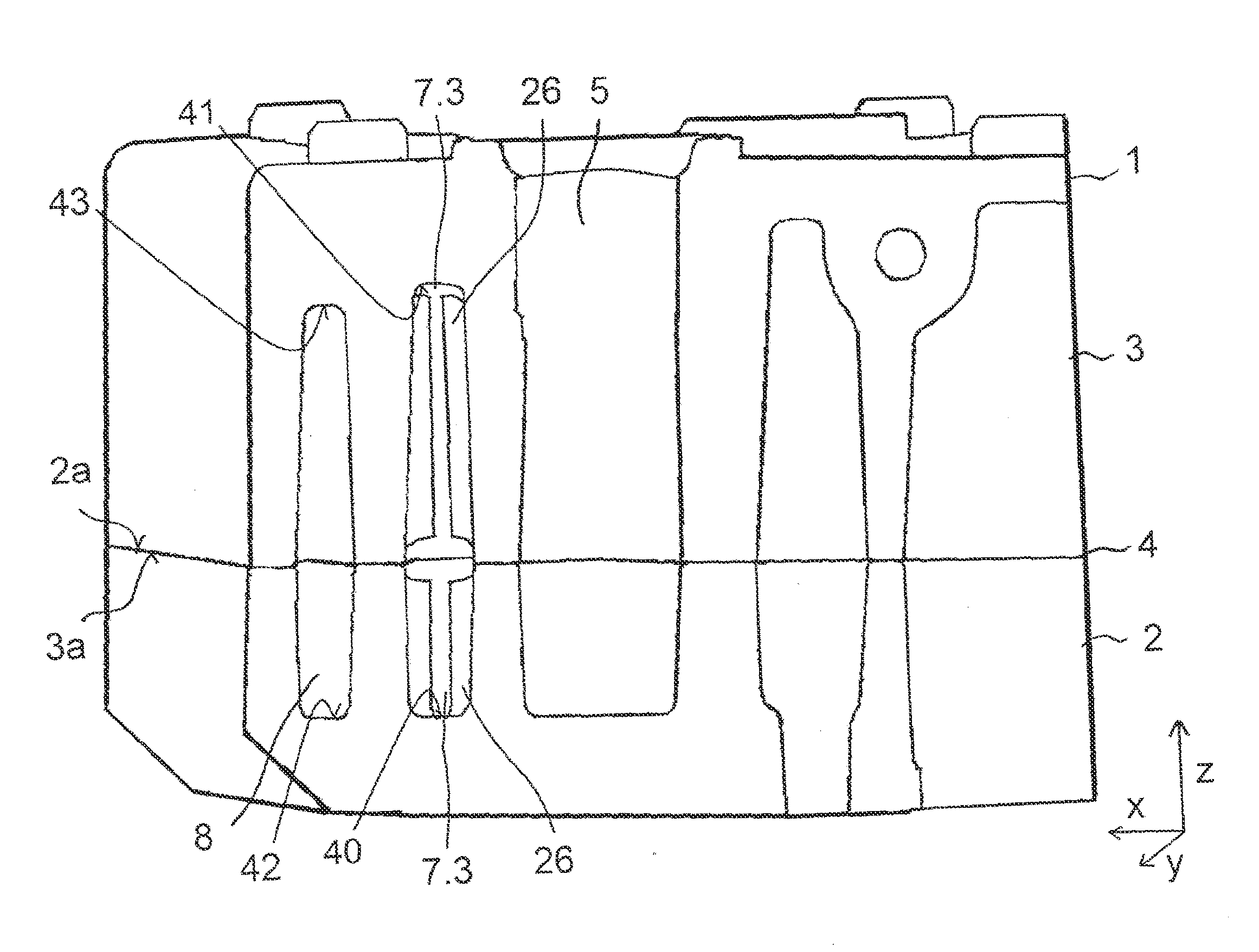
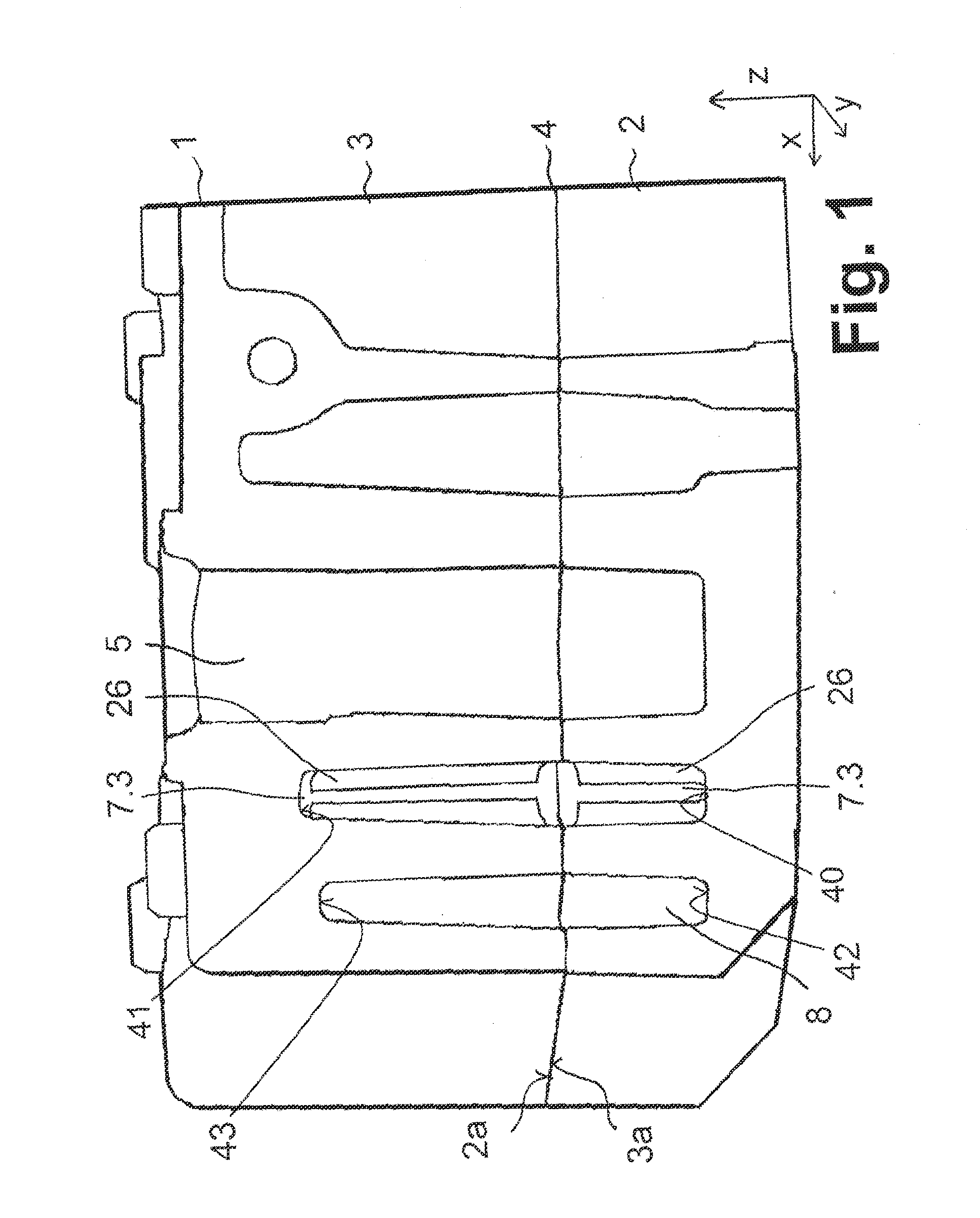
[0026]FIG. 1 shows, in cross-section, a compressor 1 comprising a manifold 2, a cover 3, and a gasket 4 disposed between the manifold 2 and the cover 3. The manifold 2 and the cover 3 are formed from metal, e.g., by a die casting process, and form a compressor block with several passages and at least one cylinder bore 5 for accommodating a piston.

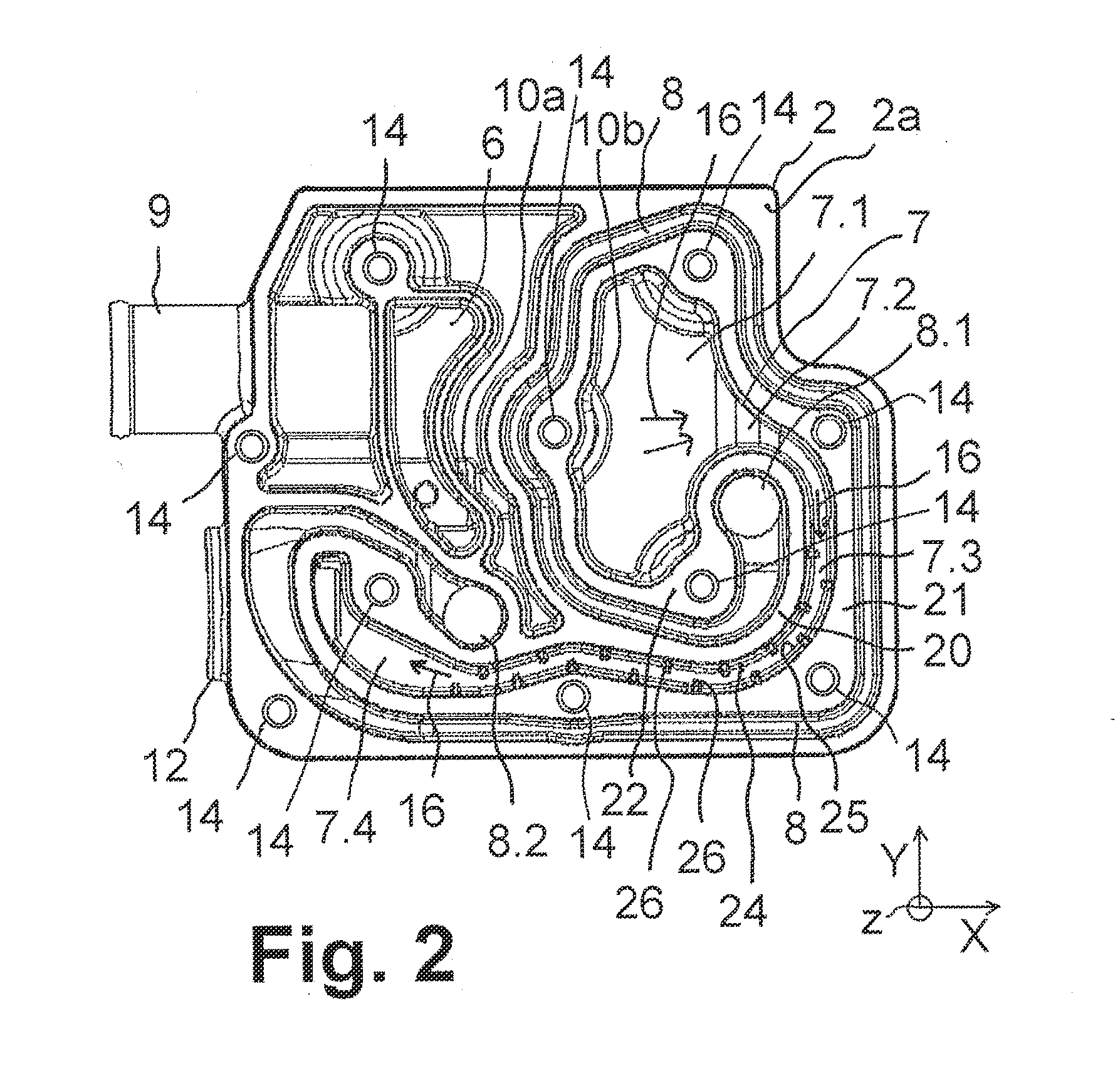
[0027]The cylinder bore 5, an inlet air passage 6, a discharge air passage 7, and at least one coolant channel 8 are formed in both the manifold 2 and the cover 3. An exemplary layout of the cylinder bore 5, the inlet air passage 6, the discharge air passage 7, and the coolant channel 8 is shown in the top view of the manifold 2 depicted in FIG. 2. The gasket 4 serves to seal the cylinder bore 5 and the passages 6, 7 with respect to each other.

[0028]Referring back to FIG. 1, the manifold 2 and the cover 3 are shown stacked together in vertical direction Z with the gasket 4 between them in order to seal the channel system described herein. T...


PUM


Abstract

A compressor for a vehicle air supply system includes a manifold, a cover, a gasket, an inlet, and an outlet. The manifold and cover are fixedly stacked together, and define a fluid channel system between them. The gasket extends laterally from between the manifold and cover. The fluid channel system includes an inlet air passage extending from the inlet to a cylinder inlet, a discharge air passage extending from a cylinder outlet to the outlet for discharging compressed air to the outlet, and one or more coolant channels that can be fed with a coolant to cool least the discharge air passage. The inlet air passage, the discharge air passage, and the coolant channel(s) extend laterally, defined by wall faces of the discharge air passage. The wall faces comprise turbulator fins protruding into the discharge air passage. The turbulator fins create turbulence in the discharged compressed air flow.

Description

FIELD OF THE INVENTION[0001]The present invention generally relates to an improved compressor for an air supply system of a vehicle, such as, for example, a utility vehicle.BACKGROUND OF THE INVENTION[0002]Vehicle air supply systems are provided for supplying compressed air to pneumatic systems such as pneumatic brakes, pneumatic suspension systems and pneumatic assistance devices in the vehicle. A compressor of a vehicle air supply system generally comprises a compressor block (cylinder block) with an air channel system and a cylinder piston unit. The air channel system provides an inlet air passage, a discharge air passage, at least one coolant channel, and, preferably, a cylinder bore.[0003]Air is sucked through an inlet, for example an inlet flange and the inlet air passage, to a cylinder inlet of the cylinder piston unit in which the air is compressed. The compressed air is then delivered from a cylinder outlet through the discharge air passage to an outlet, for example an outl...

Claims


Application Information

Patent Timeline
Patent Type & Authority Applications(United States)
IPC IPC(8): F04B53/08
CPCF04B53/08F04B39/06F04B39/064F04B39/123F04B39/125
Inventor CHADWICK, THOMASKLATT, MICHAELPAI, RAMESHWOLVERTON, STEVEN
Owner WABCO COMPRESSOR MFG
Why Eureka
Try Eureka