
Transmission apparatus and control signal mapping method

a technology of transmission apparatus and control signal, which is applied in the direction of transmission path division, channel coding adaptation, power management, etc., can solve the problems of inability to know whether or not mu-mimo is actually performed, and the amount of resources for the crss of each radio communication terminal apparatus is difficult to change, so as to achieve high transmission rate communication

Active Publication Date: 2017-07-04
PANASONIC INTELLECTUAL PROPERTY CORP OF AMERICA
View PDF8 Cites 8 Cited by
  • Summary
  • Abstract
  • Description
  • Claims
  • Application Information

AI Technical Summary

Benefits of technology

This patent allows for a unique mapping pattern for each device, which means that the signals can be adjusted for each user's environment to improve communication speed.

Problems solved by technology

For this reason, it is difficult to change the amount of resources for the CRSs for each radio communication terminal apparatus (hereinafter, abbreviated as “terminal,” which may be also called a user equipment (UE)).
However, each terminal is only aware of allocation for the terminal and thus cannot know whether or not MU-MIMO is actually performed.

Method used


Image

  • Transmission apparatus and control signal mapping method
  • Transmission apparatus and control signal mapping method
  • Transmission apparatus and control signal mapping method

Examples


operation example 1

New Carrier Type (NCT) in which Neither CRS nor PDCCH is Mapped

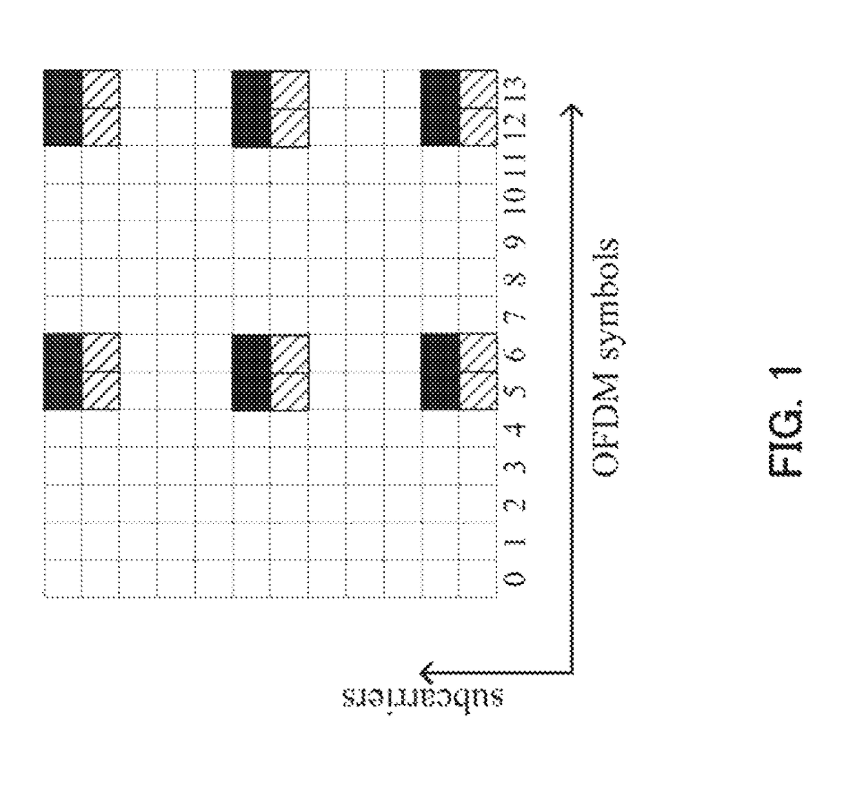
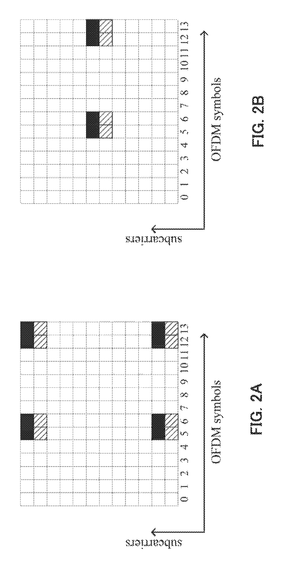
[0055]In this example, the all-0 bit sequence is defined to indicate that DMRSs are mapped on the top two OFDM symbols. FIG. 6A is a diagram illustrating an example of a DMRS mapping pattern of this operation example.

[0056]In NCT, the operation is supposedly performed using a DMRS and an enhanced PDCCH (EPDCCH) to be demodulated using the DMRS, without mapping any CRS or PDCCH. LTE-Advanced is designed assuming that a DMRS is mapped in a subframe in which a CRS and a PDCCH to be demodulated using the CRS are mapped. Since a PDCCH is mapped on the top OFDM symbol of a subframe, a DMRS is mapped on an OFDM symbol other than the top OFDM symbol. In NCT in which no PDCCH is mapped, using the top OFDM symbol for a PDSCH has been discussed.

[0057]However, when a PDSCH is mapped on the top OFDM symbol, the interval between the PDSCH and a DMRS becomes large. As a result, there arises a concern that channel estimation accuracy is...

operation example 2

[0058]In this operation example, the all-0 bit sequence is defined to indicate that DMRSs are mapped in every other RB pair. FIG. 6B is a diagram illustrating an example of a DMRS mapping pattern of this operation example. In this operation example, DRMSs are mapped only in even RB pairs and no DMRS is mapped on any odd RB pairs. Accordingly, the number of REs in which DMRSs are mapped can be reduced to approximately half.

operation example 3

[0059]In this operation example, the all-0 bit sequence is defined to indicate that a PDSCH is demodulated using a CRS. FIG. 6C is a diagram illustrating an example of a DMRS mapping pattern of this operation example. In this operation example, no DMRS is mapped but CRSs are mapped, instead. This operation example is particularly effective for a backward compatible carrier type (BCT), which allows connection of all the terminals compliant with releases 8 to 11. Since BCT includes a subframe in which CRSs are transmitted, when precoding for a PDSCH in the subframe can be the same as that for the CRSs, all the REs that are supposed to be used for DMRSs can be used for the PDSCH. Thus, the channel estimation accuracy can be maintained even when DMRS reduction is performed.

[0060](Method for Indicating DMRS Mapping Pattern)

[0061]Hereinafter, a description will be provided regarding a method for indicating a DMRS mapping pattern to a terminal from a base station in Embodiment 1.

[0062](Opt...


PUM


Abstract

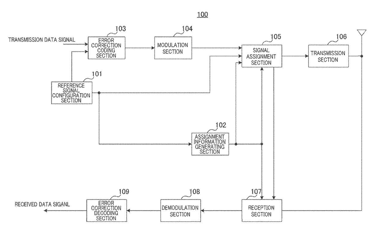
Disclosed is a transmission apparatus which enables high transmission-rate communication by mapping DMRSs in a way adapted to the reception environment of each terminal. The transmission apparatus includes: reference signal configuration section (101) that configures a DMRS mapping pattern for each terminal and outputs a DMRS and information indicating the DMRS mapping pattern; and transmission section (106) that transmits a transmission signal including the information indicating the DMRS mapping pattern configured by reference signal configuration section (101) and the DMRS mapped according to the DMRS mapping pattern to the terminal.

Description

TECHNICAL FIELD[0001]The present invention relates to a transmission apparatus and a control signal mapping method.BACKGROUND ART[0002]In recent years, transmitting not only speech data but also large volume data such as still image data and moving image data has become common along with the increasing adoption of multimedia-enabled information in cellular mobile communication systems. Meanwhile, studies have been actively carried out to achieve high transmission-rate communication using a wide radio band, multiple-input multiple-output (MIMO) transmission technology, and interference control technique in long term evolution advanced (LTE-Advanced).[0003]In addition, studies have been carried out on achieving a high transmission rate at hotspots through deployment of small cells, each being a radio communication base station apparatus (hereinafter, abbreviated as “base station”) using low transmission power in cellular mobile communication systems. Allocating a frequency different f...

Claims


Application Information

Patent Timeline
Patent Type & Authority Patents(United States)
IPC IPC(8): H04W72/04H04L27/26H04L1/00H04L5/00H04B7/08H04W52/32H04B7/06
CPCH04B7/086H04B7/068H04B7/0684H04B7/0851H04L1/0001H04L5/0033H04L5/0035H04L5/0042H04L5/0051H04L5/0094H04L27/2646H04W52/325H04W72/042H04L25/0226H04B7/0452H04L1/0003H04L1/0009H04L5/0007H04L5/0026H04L5/0073H04W72/23
Inventor HORIUCHI, AYAKOGOLITSCHEK EDLER VON ELBWART, ALEXANDERSUZUKI, HIDETOSHITAKEDA, KAZUKIWANG, LILEI
Owner PANASONIC INTELLECTUAL PROPERTY CORP OF AMERICA
Learn More