Eureka AIR delivers breakthrough ideas for toughest innovation challenges, trusted by R&D personnel around the world.

Method for controlling inkjet printing apparatus

a technology of inkjet printing and control method, which is applied in the field of controlling inkjet printing apparatus, can solve the problems of difficult discharge defect and inability to straighten out the ink, and achieve the effects of suppressing the precipitation of solid content in the ink, suppressing the lowering of production efficiency, and reducing wasteful spa

Active Publication Date: 2017-07-18
MIYAKOSHI PRINTING MACHINERY
View PDF20 Cites 4 Cited by
  • Summary
  • Abstract
  • Description
  • Claims
  • Application Information

AI Technical Summary

Benefits of technology

[0022]In the method for controlling an inkjet printing apparatus of the present invention, by performing the vibrating step to all the nozzles, even if a nozzle is not used, a discharge defect of the nozzle can be prevented in preparation for the next printing. That is, even if ink on a nozzle surface gradually evaporates due to the vibrating step, the ink in the nozzle chamber is stirred by the vibrations, so that precipitation of the solid content in the ink can be suppressed.
[0023]Thereby, for example, even if a change between images to be printed is performed and a change between nozzles to be used is performed according to a lot exchange of products to be printed or the like, a nozzle which is not used until then can be used immediately under an optimal condition.
[0024]Now, when the printing head is a line head of a fixed type, since the printing head itself is unmovable, a discharge defect tends to occur in a nozzle which is being not used particularly easily as compared with one in the above line head of a serial type.
[0025]Therefore, an effect obtained by the vibrating step in this case become considerably large.
[0026]Further, in the above method for controlling an inkjet printing apparatus, when printing is performed on an elongated printing medium, a wasteful space can be reduced and lowering of a production efficiency can be suppressed by alternately performing the discharging step and the vibrating step under an optimal condition.
[0027]Furthermore, in the above method for controlling an inkjet printing apparatus, since it is unnecessary to set a vibrating step for each nozzle, unlike the conventional art, printing data can be made relatively simple.

Problems solved by technology

As a result, when the nozzle is used, there is a possibility of causing such a discharge defect that the ink cannot be discharged straightly due to clogging in the nozzle or a partial clogging therein.
According to such an image-forming apparatus, prior to performing printing on a certain page, by swinging a meniscus of a nozzle corresponding to a printed pixel and maintaining a meniscus of a nozzle corresponding to a pixel which is not printed in a resting state, a discharge defect is hard to occur when printing is performed on the next page using a nozzle which did not discharge in printing the previous page.

Method used


Image

  • Method for controlling inkjet printing apparatus
  • Method for controlling inkjet printing apparatus
  • Method for controlling inkjet printing apparatus

Examples


Embodiment Construction

[0043]Hereinafter, with reference to the Figures, if necessary, preferred embodiments of the present invention will be described in detail. It should be noted that in the Figures, identical elements are denoted by identical reference signs so that the same description is not repeated. In addition, positional relationships, such as top and bottom or right and left, are based upon positional relationships in the Figures, unless otherwise noted. Further, the dimensional ratios of the drawings and ratios of illustrations are not limited to those shown in the Figures.

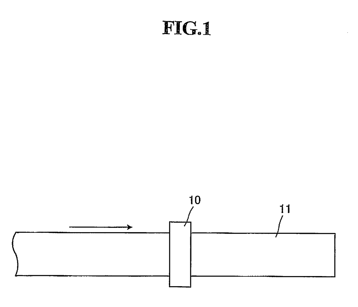
[0044]FIG. 1 is a schematic top view showing a printing head of an inkjet printing apparatus and a printing medium used in a method for controlling an inkjet printing apparatus according to an embodiment of the present invention.

[0045]As shown in FIG. 1, in an inkjet printing apparatus used in the method for controlling an inkjet printing apparatus according to the embodiment, printing is performed on a continuous elongated ...


PUM


Abstract

A method for controlling an inkjet printing apparatus performing printing to an elongated printing medium 11, the method having a discharging step of performing continuous application to a piezoelectric element 23 of a nozzle to be used with a pulse number of two or more waves per one printing element to deform the piezoelectric element and thereby discharge ink in an ink chamber 22 from an opening portion 21, and a vibrating step of performing application of the piezoelectric elements 23 to all the nozzles with a pulse number of one wave per one printing element to deform the piezoelectric elements, thereby imparting only vibrations to the inks in the ink chambers 22 without discharging the inks, where the discharging step and the vibrating step are performed alternately.

Description

TECHNICAL FIELD[0001]The present invention relates to a method for controlling an inkjet printing apparatus, and in particular to a method for controlling an inkjet printing apparatus which prevents discharge defects in all of the nozzles and is also excellent in production efficiency.BACKGROUND ART[0002]In an inkjet printing system of a piezo system, ink filled in an ink chamber is pushed out due to deformation of a piezoelectric element applied with a voltage so that ink is discharged from a nozzle.[0003]Now, in the inkjet printing apparatus, since printing is performed to form an image, of course, printing is not performed to a portion where an image is absent.[0004]Therefore, such an event occurs that even if a nozzle by which printing is not performed is in operation of the inkjet printing apparatus, ink on a nozzle surface (particularly, a meniscus portion) gradually evaporates and the ink dries so that solid content in the ink precipitates to adhere to an opening portion of t...

Claims


Application Information

Patent Timeline
Patent Type & Authority Patents(United States)
IPC IPC(8): B41J2/14B41J2/045
CPCB41J2/14233B41J2/04541B41J2/04581B41J2/04588B41J2/04596
Inventor IZAWA, HIDEOKATAGIRI, YASUSHIKOMATSUDA, SEIJI
Owner MIYAKOSHI PRINTING MACHINERY
Why Eureka
Eureka Blog
Learn More