Eureka AIR delivers breakthrough ideas for toughest innovation challenges, trusted by R&D personnel around the world.

Method for controlling inkjet printing apparatus

Active Publication Date: 2016-09-15
MIYAKOSHI PRINTING MACHINERY
View PDF3 Cites 0 Cited by
  • Summary
  • Abstract
  • Description
  • Claims
  • Application Information

AI Technical Summary

Benefits of technology

The present invention is related to a method for controlling an inkjet printing apparatus. The technical effect of the invention is that it prevents discharge defect of nozzle by performing the vibrating step to all nozzle even if a nozzle is not used. This prevents solid content precipitation in the ink, which allows the nozzle to be used immediately under an optimal condition. The vibrating step also reduces wasteful space and increases production efficiency by alternating the discharging step and the vibrating step under an optimal condition. Additionally, the printing data can be made relatively simple since it is unnecessary to set the vibrating step to each nozzle.

Problems solved by technology

According to such an image forming apparatus, prior to performing printing to a certain page, by swinging a meniscus of a nozzle corresponding to a pixel printed in printing this page and maintaining a meniscus of a nozzle corresponding to a pixel which is not printed in a resting state, a discharge defect is hard to occur when printing is performed in the next page using a nozzle which did not perform discharging in printing the previous page.

Method used


Image

  • Method for controlling inkjet printing apparatus
  • Method for controlling inkjet printing apparatus
  • Method for controlling inkjet printing apparatus

Examples


Embodiment Construction

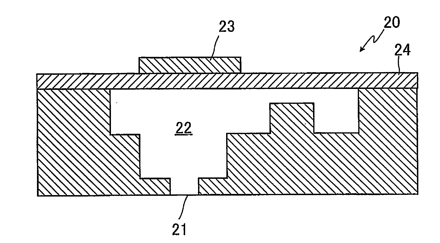
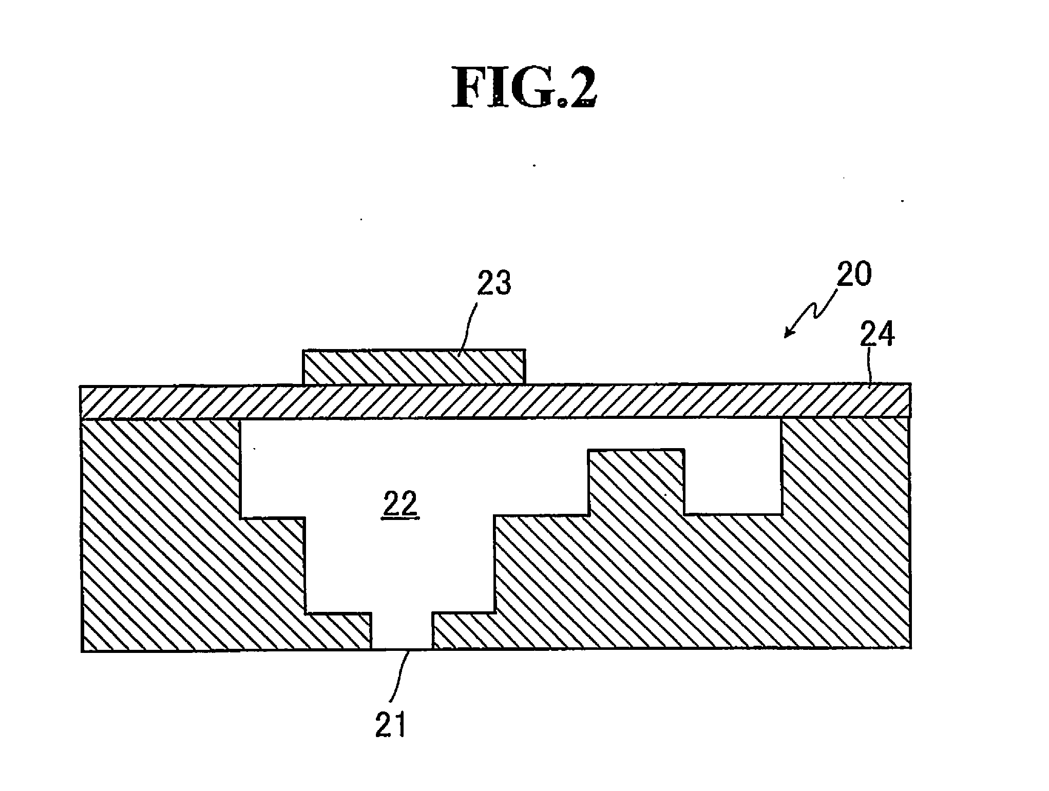
[0043]Hereinafter, with reference to Figures, if necessary, preferred embodiments of the present invention will be described in detail. It should be noted that in Figures identical elements are denoted by identical reference signs so that the same description is not repeated. In addition, positional relationships, such as top and bottom or right and left, are based upon positional relationships in Figures, unless otherwise noted. Further, dimensional ratios of the drawings and ratios of illustrations are not limited to those shown in Figures.

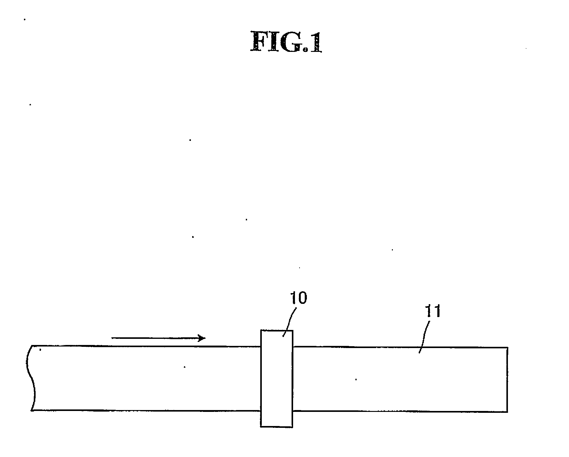
[0044]FIG. 1 is a schematic top view showing a printing head of an inkjet printing apparatus and a printing medium used in a method for controlling an inkjet printing apparatus according to an embodiment of the present invention.

[0045]As shown in FIG. 1, in an inkjet printing apparatus used in the method for controlling an inkjet printing apparatus according to the embodiment, printing is performed to a continuous elongated printing medium 11 by...


PUM


Abstract

A method for controlling an inkjet printing apparatus which can prevent nozzle discharge defects in all nozzles and is excellent in production efficiency is provided.The present invention lies in a method for controlling an inkjet printing apparatus performing printing to an elongated printing medium 11, the inkjet printing apparatus being provided with a printing head 10 having a plurality of nozzles composed of an opening portion 21 from which ink is discharged, an ink chamber 22 communicating with the opening portion 21 to accommodate ink, and a piezoelectric element 23 attached to the ink chamber 22 via a vibrating plate 24, and the method having a discharging step of performing continuous application to the piezoelectric element 23 of a nozzle to be used with a pulse number of two or more waves per one printing element to deform the piezoelectric element, thereby discharge ink in the ink chamber 22 from the opening portion 21, and a vibrating step of performing application to the piezoelectric elements 23 of all the nozzles with a pulse number of one wave per one printing element to deform the piezoelectric elements, thereby imparting only vibrations to the inks in the ink chambers 22 without discharging the inks, where the discharging step and the vibrating step are performed alternately.

Description

TECHNICAL FIELD[0001]The present invention relates to a method for controlling an inkjet printing apparatus, and in particular to a method for controlling an inkjet printing apparatus which prevents discharge defects in all nozzles and is also excellent in production efficiency.BACKGROUND ART[0002]In an inkjet printing system of a piezo system, ink filled in an ink chamber is pushed out due to deformation of a piezoelectric element applied with a voltage so that ink is discharged from a nozzle.[0003]Now, in the inkjet printing apparatus, since printing is performed to an image, of course, printing is not performed to a portion where an image is absent.[0004]Therefore, such an event occurs that even if a nozzle by which printing is not performed is in operation of the inkjet printing apparatus, medium in ink on a nozzle surface (particularly, a meniscus portion) gradually evaporates and the ink dries so that solid content in the ink precipitates to adhere to an opening portion of the...

Claims


Application Information

Patent Timeline
IPC IPC(8): B41J2/14B41J2/045
CPCB41J2/14233B41J2/04581B41J2/04541B41J2/04588B41J2/04596
Inventor IZAWA, HIDEOKATAGIRI, YASUSHIKOMATSUDA, SEIJI
Owner MIYAKOSHI PRINTING MACHINERY
Why Eureka
Eureka Blog
Learn More