
Method and circuit for determining resonant frequencies of a resonant device

a resonant device and resonance frequency technology, applied in response signal detection, solids analysis using sonic/ultrasonic/infrasonic waves, response signal detection, etc., can solve the problems of long recovery time, unfavorable material strength measurement, and inability to accurately determine the prior method, etc., to achieve a simple and accurate method of determining the resonance frequency.

Active Publication Date: 2017-07-18
STMICROELECTRONICS SRL
View PDF12 Cites 0 Cited by
  • Summary
  • Abstract
  • Description
  • Claims
  • Application Information

AI Technical Summary

Benefits of technology

[0019]A simple and very accurate method of determining a resonance frequency has been devised. The novel method may be applied for determining a resonance frequency of any resonant device, such as a shock sensor or an accelerometer.

Problems solved by technology

Unfortunately, these sensors have a mechanical resonance frequency that is close to their signal bandwidth and with amplitude that is several decibels above sensor sensitivity.
Therefore, noise at this resonance frequency may be amplified and may even dangerously saturate amplification channels causing distortion of useful signals and long recovery times.
Unfortunately, this prior method is not very accurate.
Indeed, it is relatively difficult to determine with a high precision the instants in which the output voltage of the sensor nullifies, because of external disturbances (i.e., RF interferences, running clocks) and of the limited sensitivity of zero-cross detectors.

Method used


Image

  • Method and circuit for determining resonant frequencies of a resonant device
  • Method and circuit for determining resonant frequencies of a resonant device
  • Method and circuit for determining resonant frequencies of a resonant device

Examples


Embodiment Construction

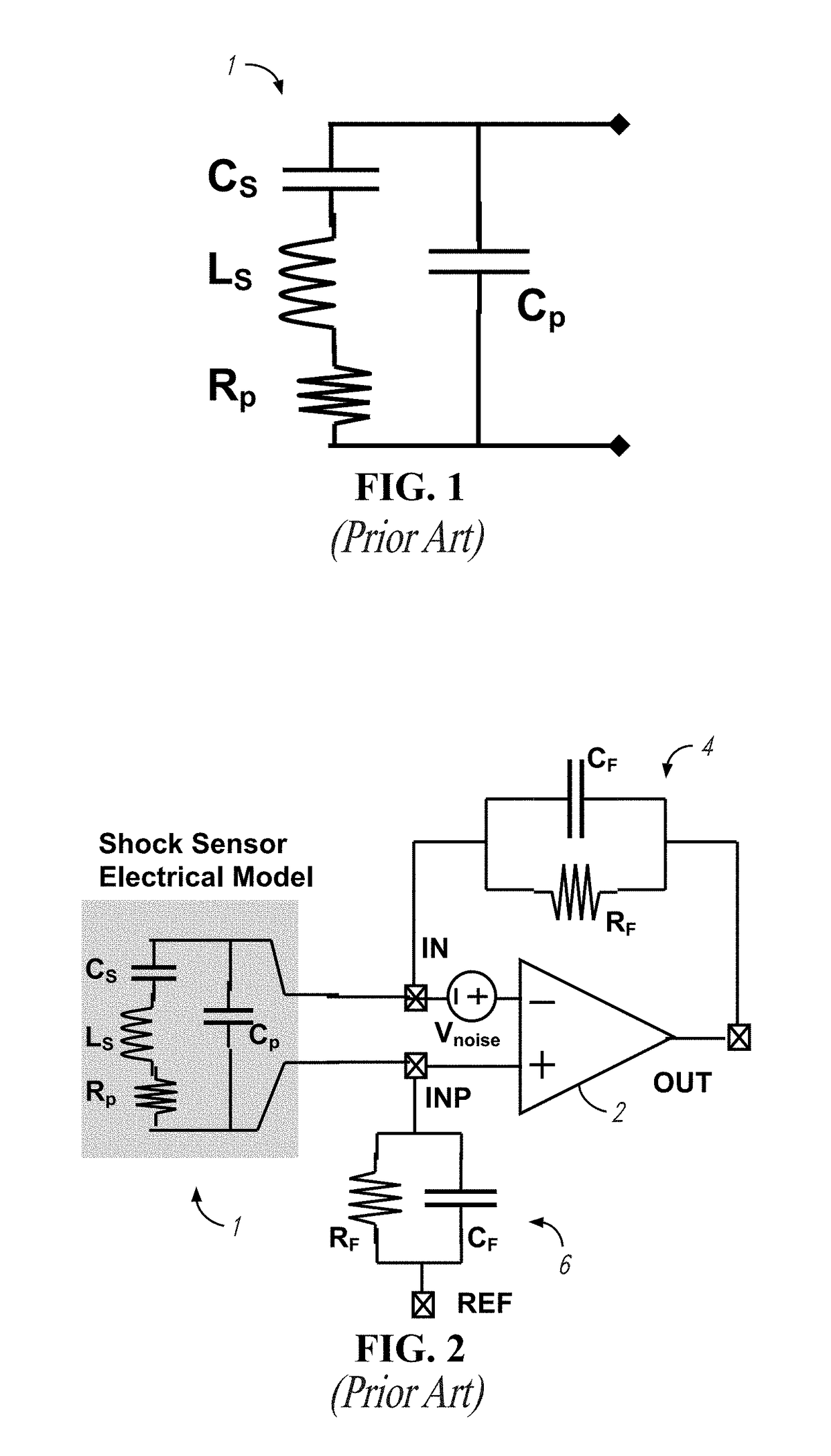
[0050]In the ensuing description reference will be made to the particular case in which the resonant device, the resonance frequency of which is to be determined, is a shock sensor coupled to a respective amplification stage as shown in FIG. 2, though the disclosed methods and circuits may be validly applied, mutatis mutandis, for determining the resonance frequency of any device.

[0051]The proposed method can be used to get information about resonance frequency for shock sensors used in hard disk drive (HDD) applications. In general, it may be used to detect a resonance frequency of a piezoelectric motion detection sensor and it can be used in conjunction with a tunable notch filter inserted at an intermediate gain stage in order to realize a system with large bandwidth and gain substantially without risks of saturating because of input noise at the resonance frequency.

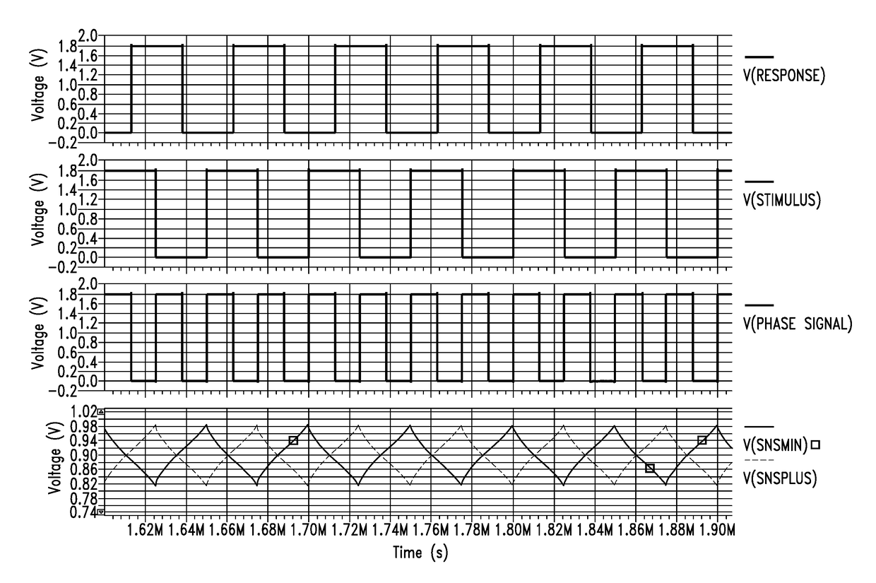
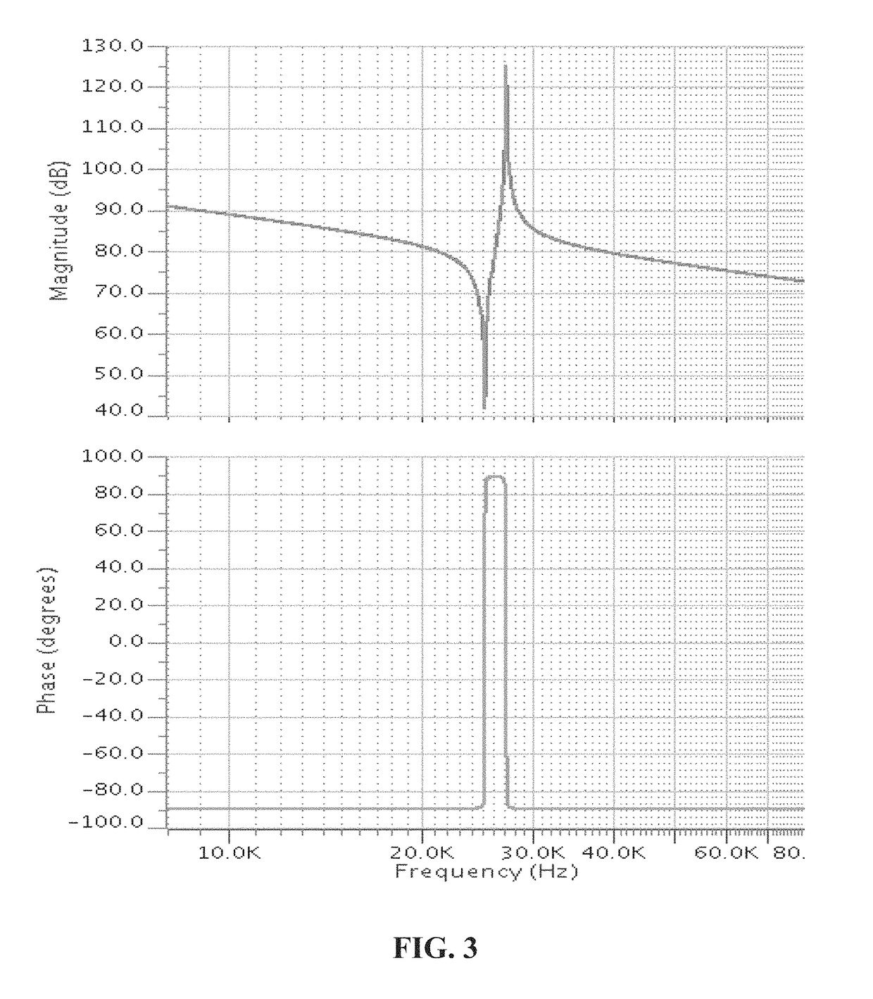
[0052]Exemplary amplitude and phase spectra of the known circuit of FIG. 2 are depicted in FIG. 4. The spectra of t...


PUM

PropertyMeasurementUnit
resonance frequencyaaaaaaaaaa
frequencyaaaaaaaaaa
phase differenceaaaaaaaaaa

Abstract

A method determines a resonance frequency of a resonant device. The method includes stimulating the resonant device with a periodic input signal having a frequency in a frequency interval; determining a frequency value for said periodic input signal in said frequency interval for which a phase-difference between said periodic input signal and a corresponding periodic output signal of the resonant device is minimum; generating a flag indicating that a resonance frequency has been determined; and generating signals representing said resonance frequency as a value of the frequency of said periodic input signal.

Description

BACKGROUND[0001]Technical Field[0002]This disclosure relates to resonance frequency detectors and more particularly to a method and a circuit for determining resonance frequencies of a resonant device, and a method of filtering an output of a resonant device.[0003]Description of the Related Art[0004]Hard disk drive (HDD) applications use shock sensors (SS) in order to avoid unwanted write-read errors due to voice coil motor (VCM) harm caused by disk displacements that are due external causes (i.e. bumps, kicks, motor driving, mechanical stresses).[0005]Unfortunately, these sensors have a mechanical resonance frequency that is close to their signal bandwidth and with amplitude that is several decibels above sensor sensitivity. Therefore, noise at this resonance frequency may be amplified and may even dangerously saturate amplification channels causing distortion of useful signals and long recovery times.[0006]Different approaches are known in literature to prevent saturation caused b...

Claims


Application Information

Patent Timeline
Patent Type & Authority Patents(United States)
IPC IPC(8): G01H11/00G01N29/36G01H13/00
CPCG01N29/36G01H11/00G01H13/00
Inventor NIZZA, NICOLOPASCALE, PAOLODIRUZZA, ANDREABOSCOLO, MICHELE BERTO
Owner STMICROELECTRONICS SRL
Learn More