
Electronic device equipped with a backlight, control method for the same, and storage medium having control program stored thereon

a technology of electronic devices and backlights, applied in static indicating devices, high-level techniques, instruments, etc., can solve the problems of disadvantageous shortening the driving time of electronic devices, large consumption of backlights and arithmetic circuits,

Active Publication Date: 2017-08-15
CASIO COMPUTER CO LTD
View PDF11 Cites 0 Cited by
  • Summary
  • Abstract
  • Description
  • Claims
  • Application Information

AI Technical Summary

Benefits of technology

[0003]The present invention relates to light source control technology suitable for an electronic device that is worn on or carried by a user.

Problems solved by technology

However, in these display devices, the power consumption of the backlight and an arithmetic circuit is generally large, whereby the driving time of the electronic device is disadvantageously shortened.

Method used


Image

  • Electronic device equipped with a backlight, control method for the same, and storage medium having control program stored thereon
  • Electronic device equipped with a backlight, control method for the same, and storage medium having control program stored thereon
  • Electronic device equipped with a backlight, control method for the same, and storage medium having control program stored thereon

Examples


first embodiment

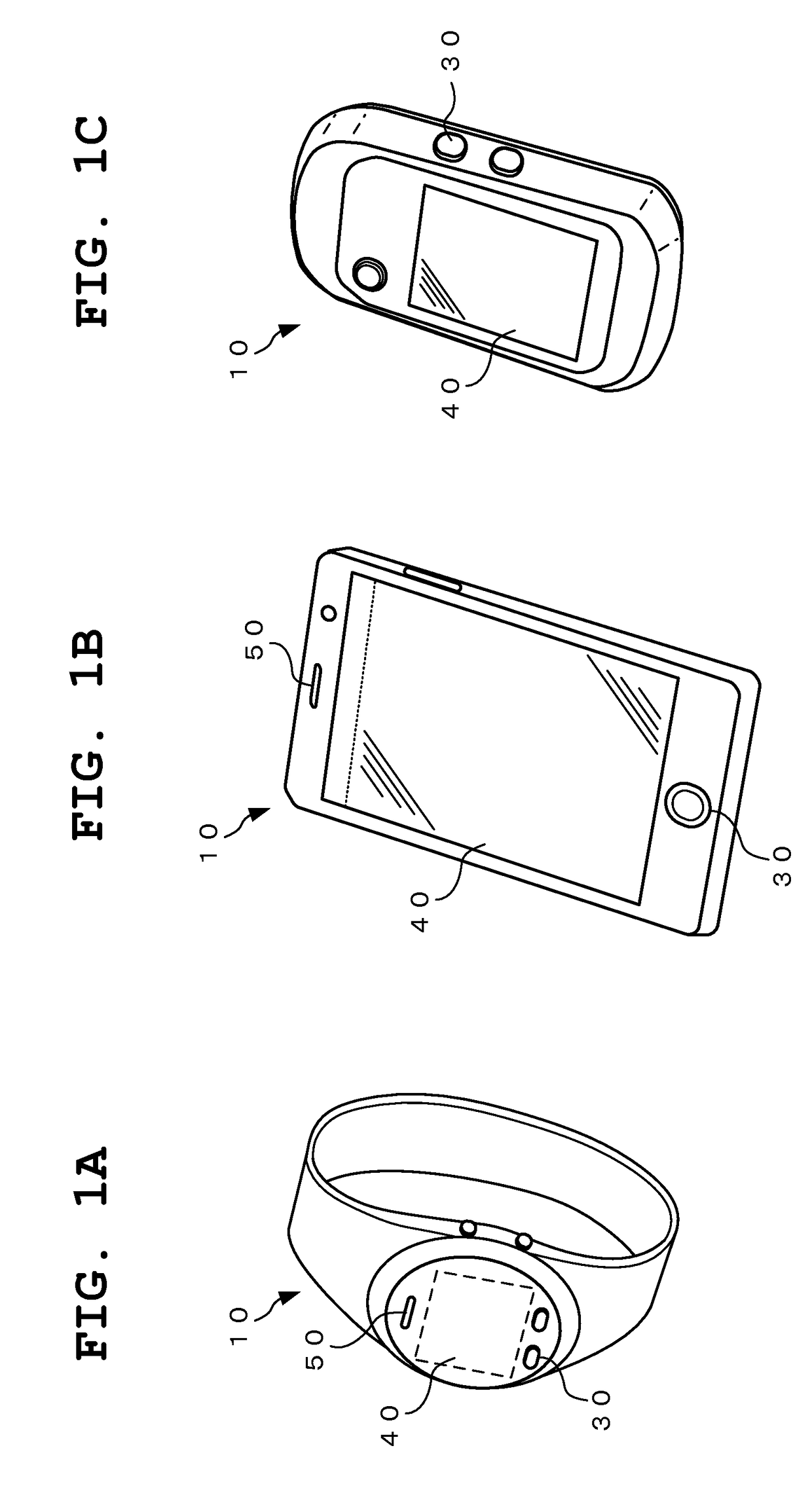
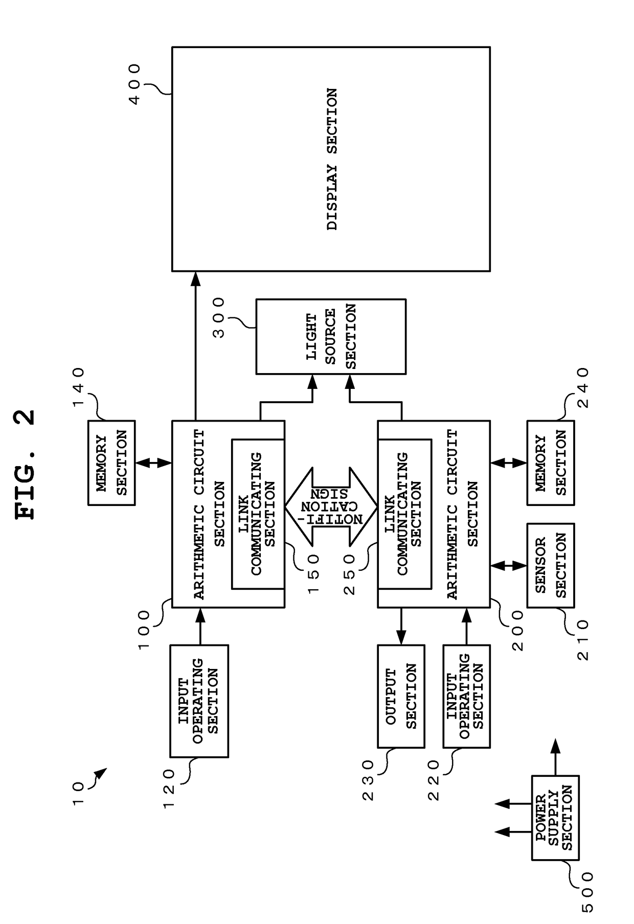
[0026]FIG. 1A to FIG. 1C are schematic perspective views of specific examples of the electronic device according to the present invention, and FIG. 2 is a schematic block diagram showing the electronic device including alight source device according to the present invention. FIG. 3A and FIG. 3B are schematic block diagrams showing an example of the light source device to be applied in the electronic device according to the present embodiment.

[0027]The electronic device 10 having the light source device according to the present invention is structured to include, for example, a display panel 40 for displaying at least various information, as depicted in FIG. 1A to FIG. 1C, This electronic device 10 may have an outer appearance of a wristwatch type or wristband type. For example, the electronic device 10 may be a sports watch or a smartwatch that is worn on the body of a user, as depicted in FIG. 1A. Also, the electronic device 10 may be a smartphone or portable telephone as depicted ...

second embodiment

[0084]Next, the electronic device including the light source device according to the present invention is described in detail with reference to the drawings.

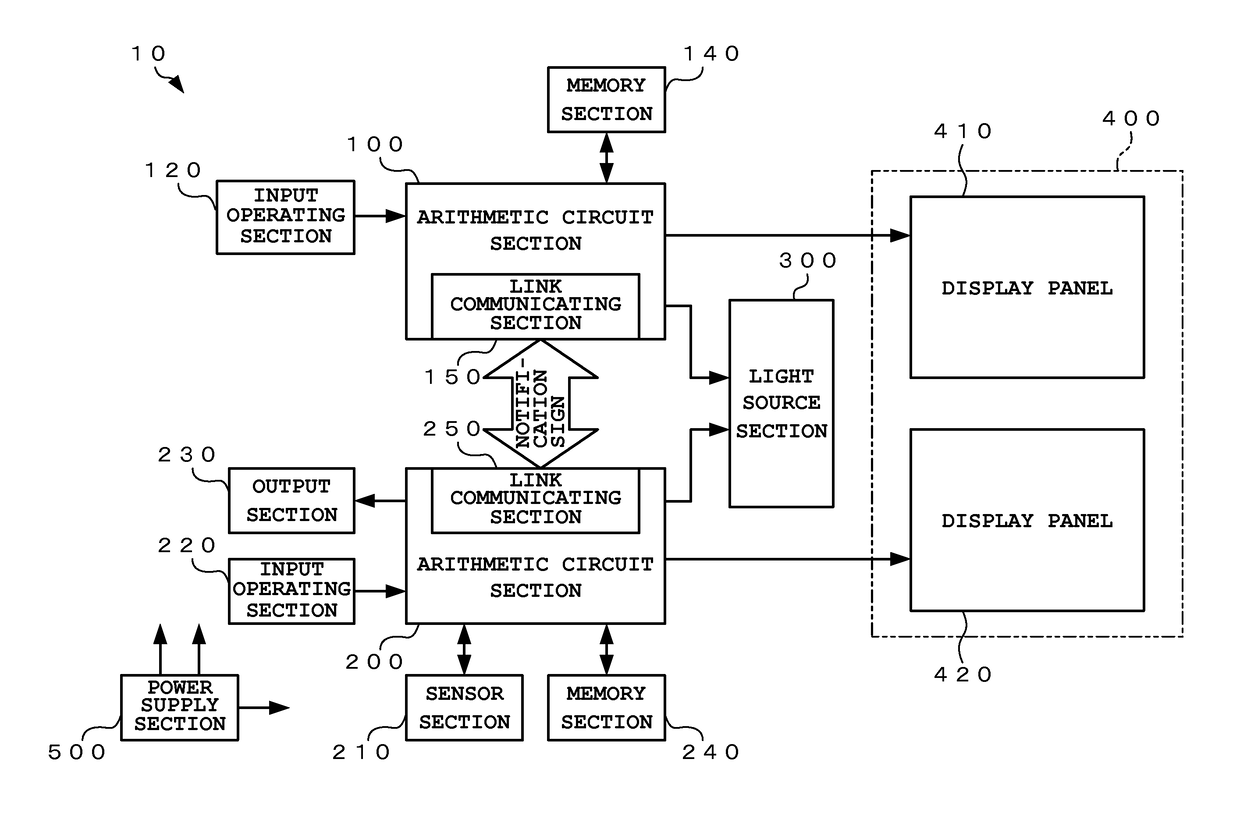
[0085]FIG. 7 is a schematic block diagram showing the second embodiment of the electronic device including the light source device according to the present invention. Here, sections equivalent to those of the above-described first embodiment are provided with the same reference numerals, and described briefly.

[0086]In the first embodiment, only one display panel is provided to the display section 400 and the display status is controlled by the arithmetic circuit section 100 having a high processing power. The second embodiment has a feature in which a plurality of (here, two) display panels are provide to the display section 400 and each of the arithmetic circuit section 100 and the arithmetic circuit section 200 controls the display status of a corresponding one of the individual display panels.

[0087]Specifically, the electroni...


PUM


Abstract

An electronic device includes a first processor, a second processor, and a light source. The first and second processors are configured such that the first processor can be shifted from a control state of controlling the light source to a non-control state of not controlling the light source and such that the second processor can be shifted from the non-control state of not controlling the light source to the control state of controlling the light source, along with a shift of the first processor from an operating state to a non-operating state.

Description

CROSS-REFERENCE TO RELATED APPLICATION[0001]This application is based upon and claims the benefit of priority from the prior Japanese Patent Application No. 2014-192390, filed Sep. 22, 2014, the entire contents of which are incorporated herein by reference.BACKGROUND OF THE INVENTION[0002]1. Field of the Invention[0003]The present invention relates to light source control technology suitable for an electronic device that is worn on or carried by a user.[0004]2. Description of the Related Art[0005]In recent years, various products to be worn on the human body have been developed for recording and analyzing various data at the time of exercise such as running, cycling, swimming, or trekking or in daily lives, and so-called sports watches that are worn on the body of the user and has a function for providing a user with exercise data or the like collected and analyzed at the time of exercise have been available on the market. Furthermore, portable electronic devices such as portable te...

Claims


Application Information

Patent Timeline
Patent Type & Authority Patents(United States)
IPC IPC(8): G09G3/34G06F1/32G06F1/16
CPCG09G3/3406G06F1/1626G06F1/1647G06F1/3215G06F1/3218G06F1/3231G06F1/3265G06F1/3293G09G2320/064G09G2320/0633G09G2330/022Y02B60/121Y02B60/1242Y02B60/1289Y02B60/32Y02D10/00Y02D30/50
Inventor SUZUKI, HIDEO
Owner CASIO COMPUTER CO LTD
Learn More