
Golf ball launch monitor target alignment method and system

a technology of golf ball launch monitor and target alignment, which is applied in the field of golf ball measurement system, can solve the problems of large error at the green and inaccurate monitor flight calculations

Active Publication Date: 2017-08-22
WAWGD NEWCO LLC
View PDF8 Cites 7 Cited by
  • Summary
  • Abstract
  • Description
  • Claims
  • Application Information

AI Technical Summary

Benefits of technology

The patent text describes a system that checks images to ensure they are aligned properly. It uses a set of edges and a threshold to identify the expected alignment stick and checks the calculated angle offset within a certain range. This system helps ensure accurate and reliable alignment.

Problems solved by technology

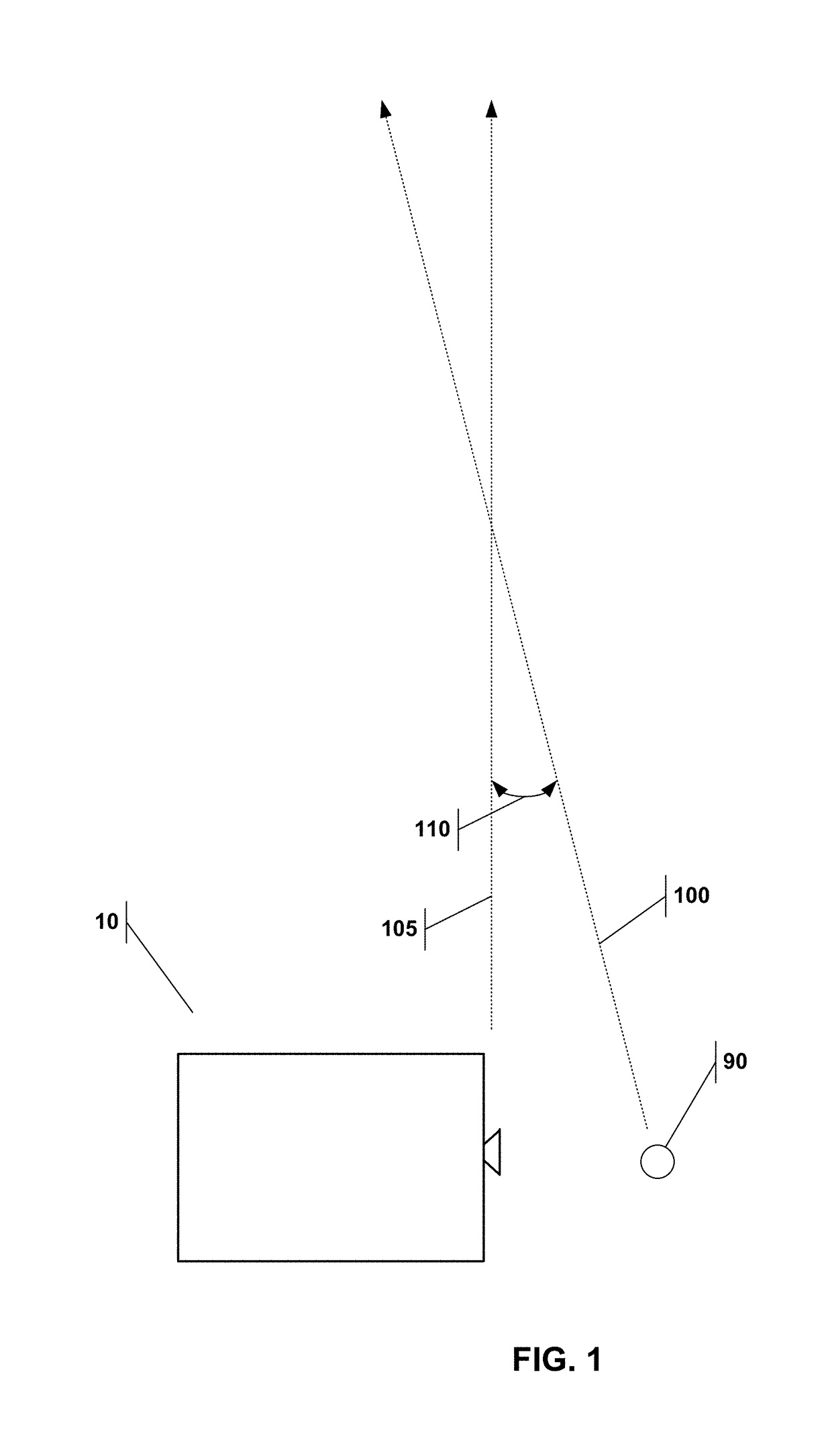
Because the golfer is attempting to reach the target (e.g. the pin), the monitor must be aligned with the target to accurately model the flight path of the ball and its ultimate position; thus without proper azimuth alignment, the monitor's calculations of the ball flight will be inaccurate.
Such an error at a tee-box can result in a very large error at the green.

Method used


Image

  • Golf ball launch monitor target alignment method and system
  • Golf ball launch monitor target alignment method and system
  • Golf ball launch monitor target alignment method and system

Examples


Embodiment Construction

[0026]Reference is made herein to some specific examples of the present invention, including any best modes contemplated by the inventor for carrying out the invention. Examples of these specific embodiments are illustrated in the accompanying figures. While the invention is described in conjunction with these specific embodiments, it will be understood that it is not intended to limit the invention to the described or illustrated embodiments. To the contrary, it is intended to cover alternatives, modifications, and equivalents as may be included within the spirit and scope of the invention as defined by the appended claims.

[0027]In the following description, numerous specific details are set forth in order to provide a thorough understanding of the present invention. Particular example embodiments of the present invention may be implemented without some or all of these specific details. In other instances, process operations well known to persons of skill in the art have not been d...


PUM


Abstract

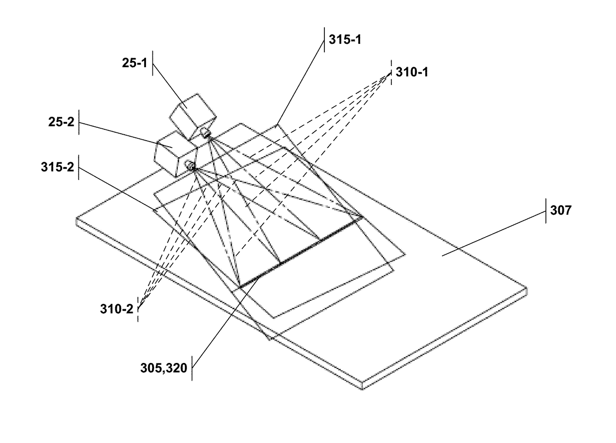
A golf ball launch monitor is disclosed that may be used with an alignment stick. The monitor has a default alignment and an image sensor adapted to capture an image of the alignment stick and communicate that image to a processor. The processor is configured to perform the following steps: (a) detect a horizontal edge within the image representative of the alignment stick by detecting large contrast changes; (b) convert each edge to a vector that starts at the sensor's focal point and projects into space based on the sensor's calibration; (c) locate the plane formed by the vectors by applying standard outlier removal and best fit analysis (d) determine the intersection of the plane and an earth tangential plane; and (e) calculate an azimuth alignment angle offset based on the line and the monitor's default alignment. The calculated azimuth alignment angle can then be used to adjust ball flight trajectory calculations.

Description

CLAIM OF PRIORITY[0001]This application claims priority to U.S. provisional application No. 62 / 422,971, entitled “GOLF BALL LAUNCH MONITOR ALIGNMENT METHOD AND SYSTEM”, which was filed on Nov. 17, 2016, priority to U.S. provisional application No. 62 / 453,454, entitled “GOLF BALL LAUNCH MONITOR TARGET ALIGNMENT METHOD AND SYSTEM” which was filed on Feb. 1, 2017, and priority to U.S. provisional application No. 62 / 477,418, entitled “GOLF BALL LAUNCH MONITOR TARGET ALIGNMENT METHOD AND SYSTEM” which was filed on Mar. 27, 2017, the contents of all of these applications are incorporated herein by reference.TECHNICAL FIELD[0002]This invention relates to a golf ball measurement systems. More particularly, the invention relates to method and system to align a golf ball launch monitor with a target such as the golf pin.BACKGROUND[0003]A golf ball launch monitor is an electronic device for assisting a golfer in improving his or her game. More particularly, the monitor is used to analyze the i...

Claims


Application Information

Patent Timeline
IPC IPC(8): A63B67/02A63F7/20A63B24/00
CPCA63B24/0021A63B2024/0031A63B2220/807A63F13/213A63F13/573A63F13/812G06T2207/30204G06T2207/30224G06T2207/30244G06T7/73A63B69/3658A63B71/0622A63B2071/0625
Inventor KIRALY, CHRIS
Owner WAWGD NEWCO LLC
Learn More