
Flow fin

a technology of flow fins and fins, which is applied in the direction of special-purpose vessels, vessel construction, canoes/kayaks, etc., can solve the problems of limited material flexibility and existing fin designs, and achieve the effect of simple structure, efficient fin shape during operation, and thicker foil section

Active Publication Date: 2017-08-22
HOBIE CAT IP LLC
View PDF37 Cites 7 Cited by
  • Summary
  • Abstract
  • Description
  • Claims
  • Application Information

AI Technical Summary

Benefits of technology

[0009]In another aspect, this invention comprises in a watercraft having propulsion means extending below the water line comprising a pair of flexible fins each having a leading edge and a trailing edge, each fin being supported at its leading edge by a mast, each fin being adapted to oscillate through an arcuate path in a generally transverse direction with respect to the central longitudinal dimension of said watercraft, and means operatively associated with said propulsion means for applying input force to said propulsion means whereby as input force is applied said flexible fins can twist to form an angle of attack for providing forward thrust with respect to the longitudinal dimension of the watercraft while moving in both directions along said arcuate path, the improvement wherein each of said fins has a thick airfoil section profile generally conforming to NACA0015 to provide more efficient propulsion.
[0029]The present invention provides an adjustable mast length which is a fin tensioning device to allow for customized peddling resistance for various operators and optimized hydrodynamic performance for different vessel lengths. The fin tension is the tension in the fin between the tip of the mast and the bottom aft corner of the fin. The fin tension affects the shape and therefore performance of the fin. Increasing the fin tension effectively makes the fin stiffer and increases the angle of attack of the fin meeting the water which creates more lift and more resistance on the pedal. The mast length adjusting device located on the tip of mast and accessible by a hole at the tip of the fin is easily adjusted by the user.

Problems solved by technology

The existing fin designs are limited to relatively soft and flexible material to allow the flex and twist to assume the shape of a propeller blade.

Method used


Image

  • Flow fin
  • Flow fin
  • Flow fin

Examples


Embodiment Construction

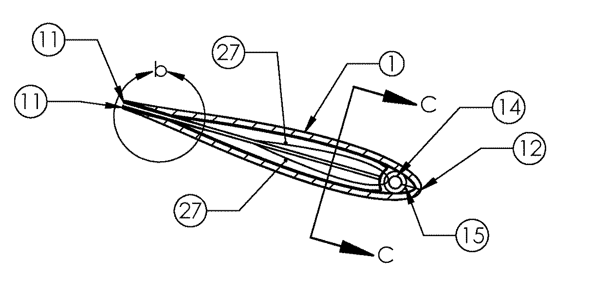
[0043]The fin 1 is essentially a thin sheet of material wrapped around the mast 2. The leading edge 12 is formed where the material is wrapped around the mast 2. The trailing edge 11 is where the two pieces of material meet. The clew 7 is a hole passing through both pieces of material of the fin at the base of the fin near the trailing edge 11. The trailing edge 11 and leading edge 12 of the fin 1 are parallel and the tip end 16 of the fin 1 is parallel to the axis of oscillation 28.

[0044]The fin can be injection molded from a single material such as pure nylon or glass filled nylon.

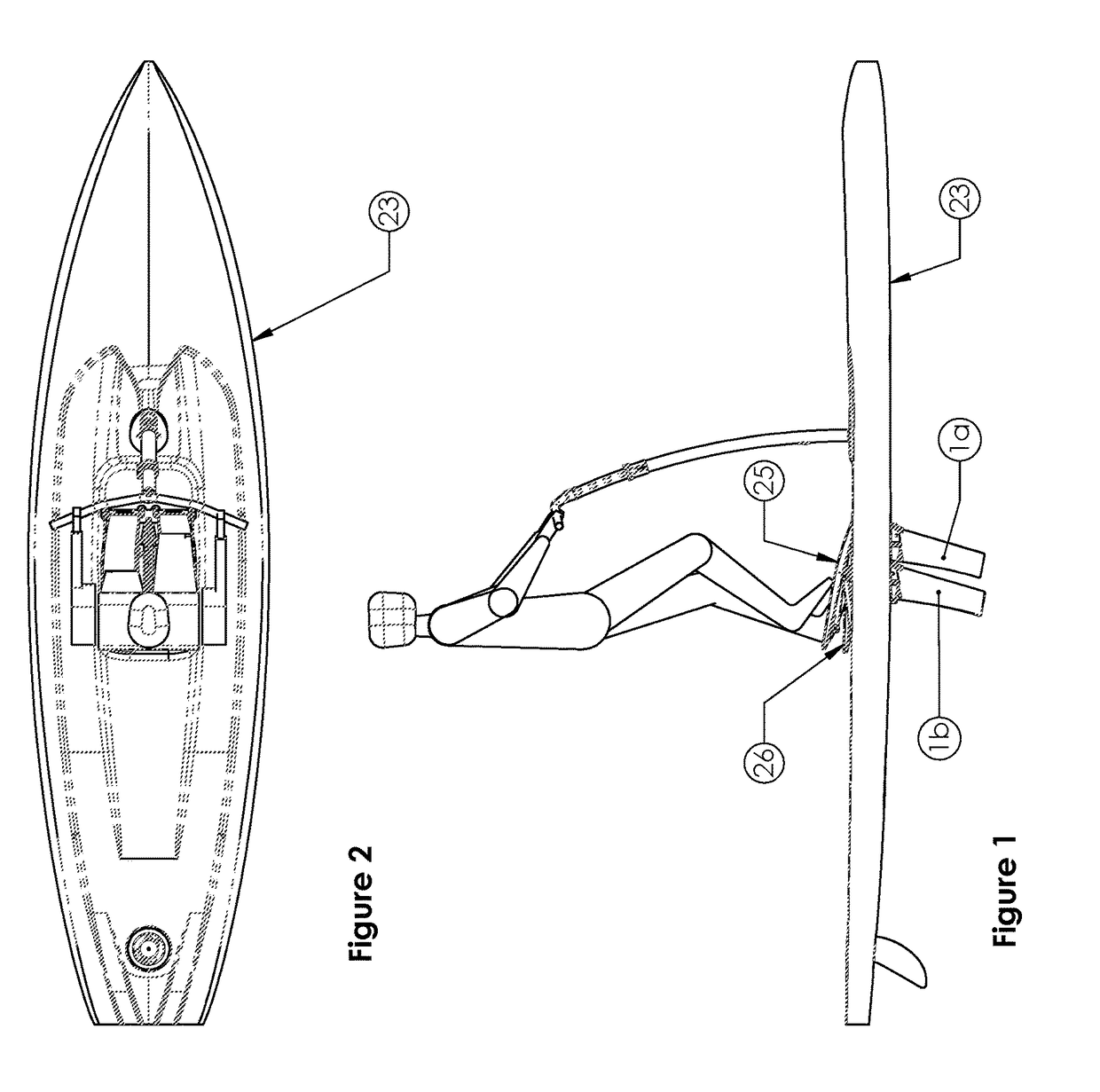
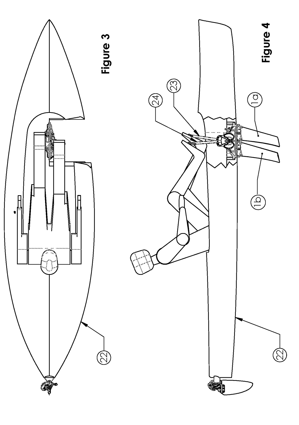
[0045]The tip end 16 includes inner pocket 15 which receives the mast 2 on which the fin 1 rotates in an oscillating fashion. The mast 2 is secured to sprocket 17 which is driven by a chain. The entire mechanism shown in the drawings of this patent is inserted through the hull of the kayak 22 or the stand up craft 23 and into the water as shown in FIG. 1 and FIG. 3.

[0046]The clew 7 of the fin 1 are conne...


PUM


Abstract

A human propelled watercraft having a pair of flexible fins supported by a mast extending into the water each adapted to oscillate through an arcuate path in a generally transverse direction with respect to the central longitudinal dimension of said watercraft. Pedals are provided for applying input force whereby as input force is applied, the flexible fins can twist to form an angle of attack for providing forward thrust with respect to the longitudinal dimension of the watercraft while moving in both directions along the arcuate path. Each of the fins preferably is composed of a layer of stiff and durable material that is wrapped around the mast. The two layers of material touch at the trailing edge and they are free to slide relative to each other. Preferably, each of the fins is provided with adjustable tensioning at the tip of the mast.

Description

[0001]This patent application claims the benefit of U.S. Provisional Patent Application 62 / 195,450, filed Jul. 22, 2015, the disclosure of which is expressly incorporated herein by reference.FIELD OF THE INVENTION[0002]The present invention relates generally to the means of propelling a vessel and more specifically it relates to the design of a thrust producing oscillating fin.BACKGROUND OF THE INVENTION[0003]Oscillating fin propulsion has been used to produce efficient propulsion. This technology appears in U.S. Pat. No. 6,022,249 and U.S. Pat. No. 7,637,791 the text and drawings of which are expressly incorporated herein by reference, which discloses a novel water craft, such as a kayak or a stand up craft, which typically include a hull having propulsion means extending below the water line. The propulsion means comprises a pair of fins each having a leading edge and a trailing edge and adapted to oscillate through an arcuate path in a generally transverse direction with respect ...

Claims


Application Information

Patent Timeline
Patent Type & Authority Patents(United States)
IPC IPC(8): B63H1/36B63H1/32B63B35/79B63H16/18B63B35/71B63H16/20
CPCB63H1/32B63B35/79B63B35/7943B63H1/36B63H16/18B63B35/71B63H2016/202B63B32/10B63B32/64B63B32/66B63B34/20
Inventor KETTERMAN, GREGORY SCOTTCZARNOWSKI, JAMES TAYLORKARDAS, JASON CHRISTOPHERDOW, PHILIP JAMESBRACKETT, DREW WILLIAMYELLIN, SHANEMYERS, III, JOHN THOMAS
Owner HOBIE CAT IP LLC
Learn More