Compound Aircraft with Autorotation

a technology of aircraft and blades, applied in the field of composite aircraft, can solve problems such as catastrophic failure of blades, and achieve the effect of stable blade rotation

Active Publication Date: 2011-02-17
PIASECKI FREDERICK W
View PDF4 Cites 79 Cited by
  • Summary
  • Abstract
  • Description
  • Claims
  • Application Information

AI Technical Summary

Benefits of technology

[0028]For a compound aircraft moving at a high forward speed, the inertial forces acting on the rotor blades due to rotation of the rotor, including autorotation of the rotor, tend to stabilize the blades while the aerodynamic forces acting on the blades due to wind pressure from the forward motion of the aircraft tend to destabilize the blades. When the rotor is rotating at a high rotational speed, the inertial forces overwhelm the aerodynamic forces, resulting in stable rotation of the blades. When the rotational speed of the rotor is too low compared to the forward speed of the aircraft, the destabilizing aerodynamic forces due to the forward motion of the aircraft may overcome the stabilizing inertial forces of the rotating blades, resulting in instability and potentially catastrophic failure of the blades.

Problems solved by technology

Instability and excess deformation of the rotor blades would cause excess vibration and could result in catastrophic failure of the blades.

Method used


Image

  • Compound Aircraft with Autorotation
  • Compound Aircraft with Autorotation
  • Compound Aircraft with Autorotation

Examples


Embodiment Construction

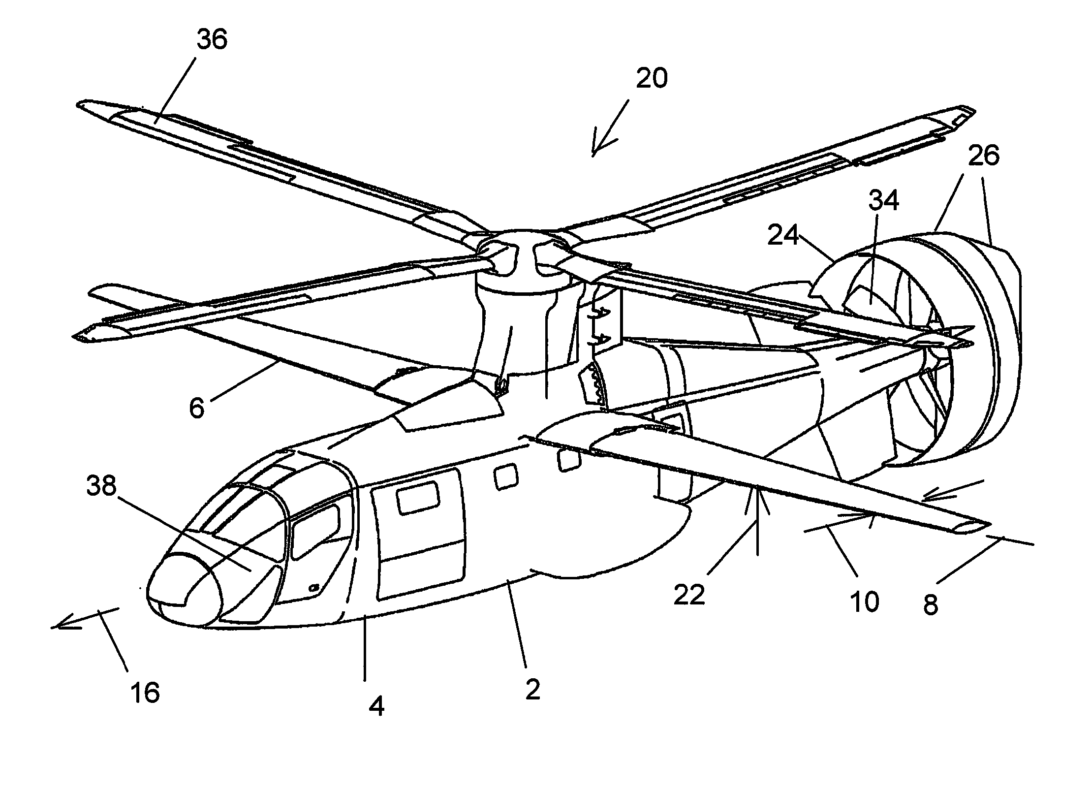
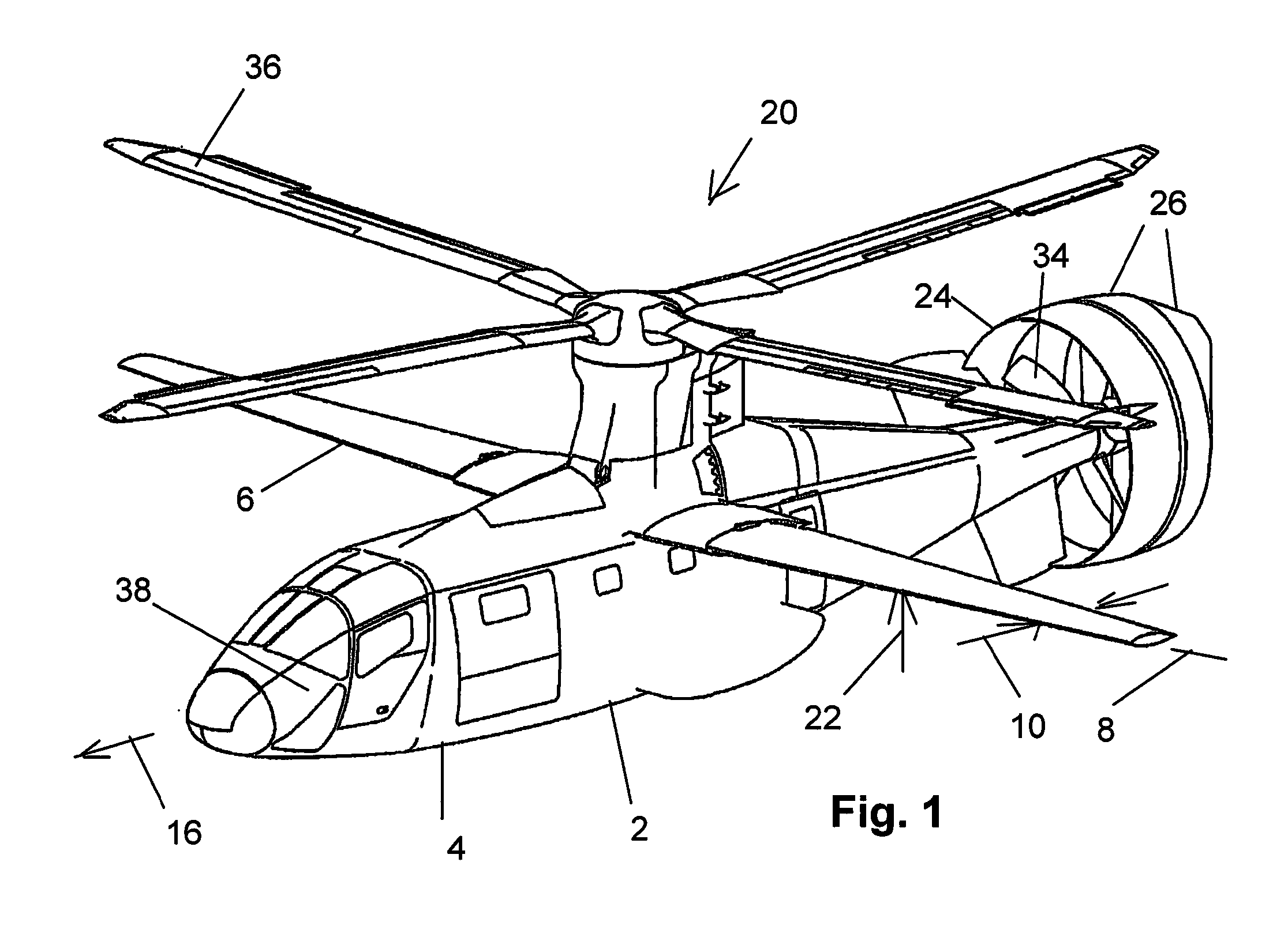
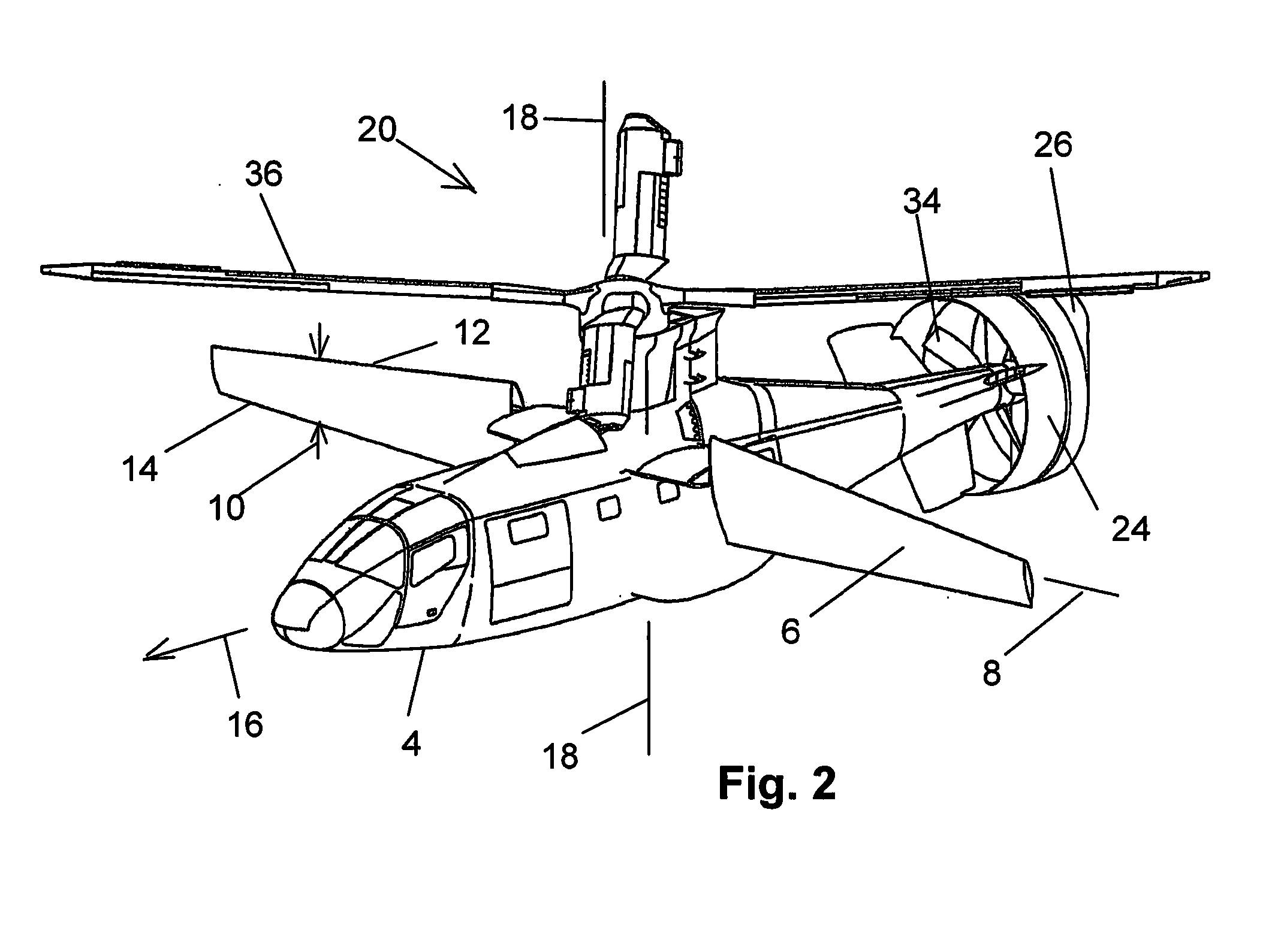
[0042]FIGS. 1-5 are views of the compound aircraft 2. The compound aircraft 2 features a fuselage 4. A variable incidence wing 6 is attached to fuselage 4. Variable incidence wing 6 is rotatable about a variable incidence wing axis of rotation 8 between a cruise position, shown by FIGS. 1, 3, 4, 5 and 6 and a hover position, shown by FIG. 2. Variable incidence wing 6 defines a chord 10 between the leading edge 12 and trailing edge 14. When the variable incidence wing is in the cruise position shown by FIG. 1, the chord 10 is oriented generally in the forward direction 16. When the variable incidence wing is in the hover position, the chord 10 is oriented generally parallel to the axis of rotation 18 of the rotor 20, as shown by FIG. 2.

[0043]When the variable incidence wing 6 is oriented with chord 10 in the forward direction 16, the variable incidence wing is configured to generate lift 22 in response to air movement over variable incidence wing 6 due to the motion of the compound a...


PUM


Abstract

A compound aircraft features variable incidence wings, a thruster, a rotor and a clutch connecting the engines to the rotor. Upon reaching a suitable forward speed, the control system of the compound aircraft unloads the rotor and disengages the clutch, disconnecting the rotor from the engines. The control system configures the cyclic and collective pitch effectors to cause the rotor to autorotate. The control system selects an autorotation rotational speed that is adequately rapid to prevent excessive deformation of the rotor blades due to aerodynamic forces acting on the blade and that is adequately slow to prevent excessive compressibility effects.

Description

I. STATEMENT OF RELATED APPLICATIONS[0001]This application is entitled to priority from U.S. Provisional Patent Application 61 / 234,051 titled “Compound Aircraft” and filed Aug. 14, 2009.II. BACKGROUND OF THE INVENTION[0002]A. Field of the Invention[0003]The Invention is a compound aircraft that utilizes autorotation of the rotor to allow reduction in the rotational speed of the rotor during flight while avoiding instability of the rotor and excess deformation of the rotor blades due to aerodynamic forces resulting from the forward motion of the aircraft. The Invention is also a method of flight utilizing the compound aircraft of the invention.[0004]B. Description of the Related Art[0005]1. Compound Aircraft[0006]A ‘compound’ aircraft is an aircraft that includes features of both fixed wing aircraft and rotary wing aircraft. The compound aircraft includes the elements of a helicopter, including at least one powered main rotor and a mechanism to overcome the torque reaction of the rot...

Claims


Application Information

Patent Timeline
Patent Type & Authority Applications(United States)
IPC IPC(8): B64C27/22B64C27/26
CPCB64C3/385B64C27/26B64C27/12B64C27/025
Inventor PIASECKI, FREDERICK W.
Owner PIASECKI FREDERICK W
Why Eureka
Try Eureka