Lock cylinder

a technology of locking cylinders and locking cylinders, which is applied in the direction of cylinder locks, building locks, constructions, etc., to achieve the effect of preventing forcible opening of locks

Inactive Publication Date: 2017-08-29
HUF HULSBECK & FURST GMBH & CO KG
View PDF23 Cites 0 Cited by
  • Summary
  • Abstract
  • Description
  • Claims
  • Application Information

AI Technical Summary

Benefits of technology

[0005]The object of the invention is therefore to provide a more secure lock cylinder which prevents forcible opening of a lock by way of an output element of a lock cylinder.
[0009]According to another preferred embodiment, it is provided that the means form a form closure with the housing. Security can thereby be further enhanced, since the forces on the tool have to be increased in order to undo the form closure between the bearing and the means. The form closure increases the resistance moment of the output element against turning when the tool which engages the output element is used.
[0010]The design is very simple and cost-effective if the housing has at least one opening and / or recess, which serves for the form closure with the cam portion assigned to the means.

Problems solved by technology

In the prior art it is disadvantageous, however, that the groove in the housing, which groove is positively connected to the cam of the disengaging sleeve, for structural reasons adjoins a central center axis of the lock cylinder.

Method used


Image

  • Lock cylinder
  • Lock cylinder
  • Lock cylinder

Examples


first embodiment

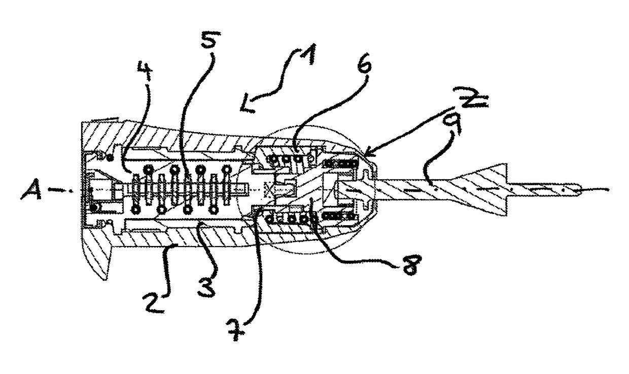
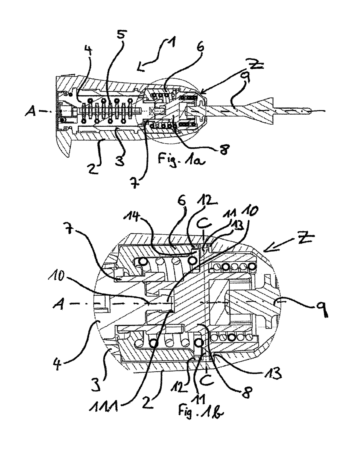
[0027]A lock cylinder 1 is represented in FIGS. 1a to 1c and 2a to 2c. In FIG. 1a, the lock cylinder 1 is shown in a proper use.

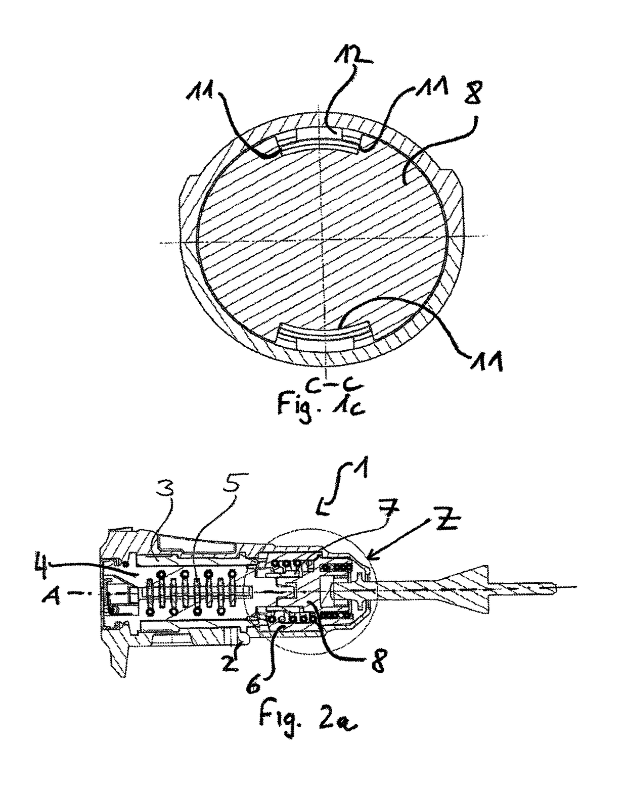
[0028]A proper use exists if a lock (not shown in detail) operatively connected to the lock cylinder 1 can be opened and closed with a proper key assigned to the lock cylinder 1. In FIG. 2a, the lock cylinder 1 according to the first embodiment is shown in an improper use. An improper use exists if the lock (not shown in detail) operatively connected to the lock cylinder 1 is attempted to be opened with a key (incorrect key) not assigned to the lock cylinder 1, or with a tool, in particular with a screwdriver.

[0029]The lock cylinder 1 shown in FIGS. 1a, 2a and 1b, 2b has a housing 2, in which a metallic sleeve 3 having a cylinder core 4 accommodated therein is rotatably mounted. The cylinder core 4 has spring-loaded tumblers 5, which, when a key (not represented in detail) is removed from the cylinder core 4, form a form closure with recesses (not shown) a...

third embodiment

[0034]In FIGS. 4a and 4b, the lock cylinder 1 is represented, which lock cylinder is essentially a combination of the first and second illustrative embodiment. In addition to that form closure between bearing 8 and coupling element 7 which is shown in FIG. 3b, a form closure between the disengaging sleeve 6 and the housing 2, and the disengaging sleeve 6 with the bearing 8, is herein disclosed.

[0035]Within the scope of said illustrative embodiments, in particular with respect to the second and third illustrative embodiment, reference is made to DE 102009050905.4.


PUM


Abstract

A lock cylinder includes a housing, in which a sleeve having a cylinder core accommodated therein is rotatably supported. The cylinder core has spring-loaded tumblers forming a form closure with recesses arranged in the sleeve when a key engaging the tumblers is removed. Inside the housing, the sleeve is coupled to a coupling element by means of a disengaging sleeve. The coupling element is supported inside the housing and connected to a bearing in a rotationally-fixed manner. The bearing supports an output element. At least one of the sleeve and the coupling element forms a form closure with the bearing to block the rotation of the output element if an improper object is used in operative connection with the cylinder core.

Description

CROSS-REFERENCE TO RELATED APPLICATIONS[0001]This application is a continuation of U.S. patent application Ser. No. 13 / 505,691 filed on May 2, 2012, which claims priority to PCT International Application No. PCT / DE2010 / 075123 filed on Nov. 5, 2010, which claims priority to German Patent Application No. 10 2009 052 406.1 filed on Nov. 10, 2009, both of which are fully incorporated by reference herein.STATEMENT REGARDING FEDERALLY SPONSORED RESEARCH OR DEVELOPMENT[0002]Not applicable.FIELD OF THE INVENTION[0003]The invention relates to a lock cylinder comprising a housing, in which a sleeve having a cylinder core accommodated therein is rotatably mounted and the cylinder core has spring-loaded tumblers which form a form closure with recesses arranged in the sleeve when a key is removed, and within the housing the sleeve is coupled to a coupling element by means of a disengaging sleeve, wherein the coupling element is mounted within the housing and the coupling element is connected in ...

Claims


Application Information

Patent Timeline
Patent Type & Authority Patents(United States)
IPC IPC(8): E05B17/04E05B15/00E05B27/00E05B17/00
CPCE05B17/045E05B15/0013E05B17/04E05B17/041E05B27/0003E05B17/0058Y10T70/7672Y10T70/8486
Inventor LOW, MATTHIAS
Owner HUF HULSBECK & FURST GMBH & CO KG
Why Eureka
Try Eureka