
Mid-point indicator lace

Active Publication Date: 2017-09-26
ALESHKA ADAM A +1
View PDF12 Cites 2 Cited by
  • Summary
  • Abstract
  • Description
  • Claims
  • Application Information

AI Technical Summary

Benefits of technology

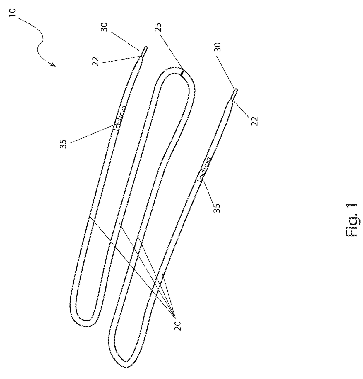
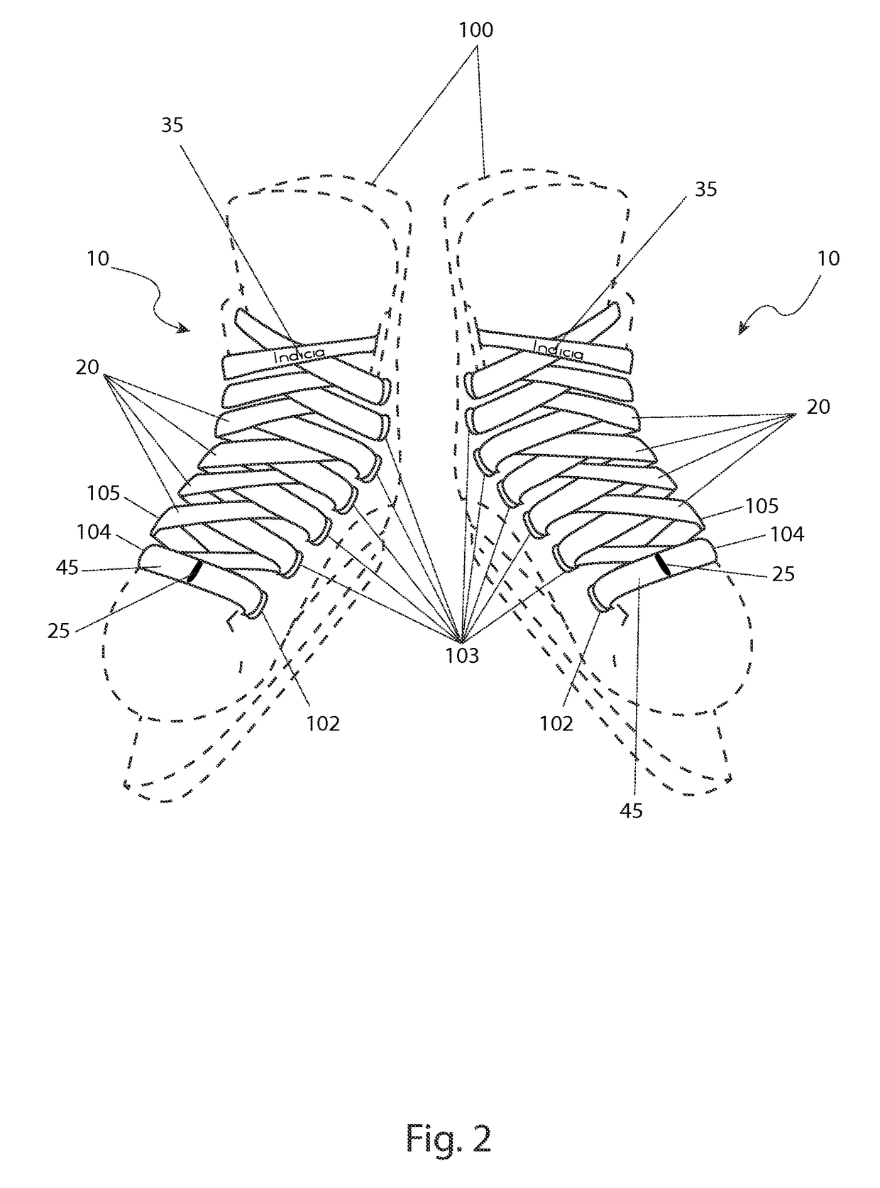
The present invention provides a lace with a stitched or printed center point indicator, making it easy for users to find the center point. The lace also has aglets on the ends, which helps users to evenly thread the lace through the eyelets and tie them together while ensuring the ends points are equidistant from the center location of the footwear. This prevents snagging or unwanted unraveling of the tied lace and helps to retain the footwear on the foot of the user. Overall, the present invention improves upon the prior art by making it easier and more efficient to use.

Problems solved by technology

In these cases in particular, if the center pint of the lace is unknown or moves, or is otherwise lost during the lacing of the footwear the lace must be rethreaded with time and energy lost to the effort.
Further, a mis-lacing can cause snagging or unwanted unraveling of the tied lace, which hampers the ability to retain the footwear on the foot of the user.

Method used


Image

  • Mid-point indicator lace
  • Mid-point indicator lace
  • Mid-point indicator lace

Examples


Embodiment Construction

[0027]The best mode for carrying out the invention is presented in terms of its preferred embodiment, herein depicted within FIGS. 1 through 6. However, the invention is not limited to the specifically described embodiment. A person skilled in the art will appreciate that many other embodiments of the invention are possible without deviating from the basic concept of the invention. Any such work around will also fall under scope of this invention. While only one particular configuration is shown and described that is for purposes of clarity and disclosure and not by way of limitation of scope.

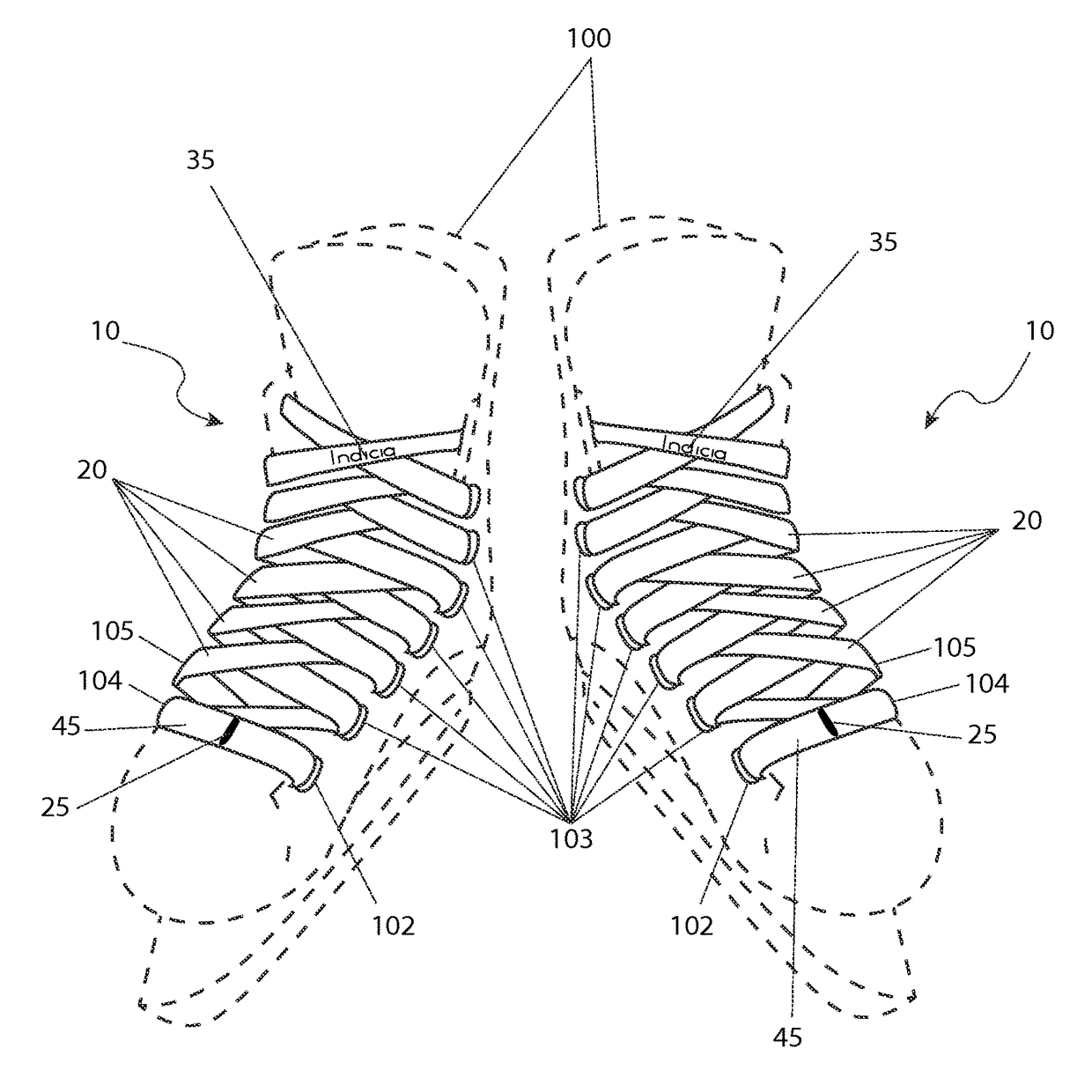
[0028]The present invention describes a lacing assembly (herein described as the “device”) 10, which provides a visual mid-point indicator 25 at a center point thereof. The device 10 can be provided in multiple embodiments such as, but not limited to a: shoe lace, shoestring, rope, cord, twine, or the like. The device 10 reduces time required and improves centering accuracy while installing the...


PUM


Abstract

A lace including a stitched or printed center point indicator enables a user to visually locate the center point of the lace. The lace further having a pair of aglets affixed on the distal ends thereof.

Description

RELATED APPLICATIONS[0001]The present invention was first described in and claims the benefit of U.S. Provisional Application No. 61 / 898,699, filed Nov. 1, 2013, the entire disclosures of which are incorporated herein by reference.FIELD OF THE INVENTION[0002]The present invention relates generally to laces for footwear including a center point indicator.BACKGROUND OF THE INVENTION[0003]When lacing footwear or other articles with lace, where it is imperative that the ends of the lace are equidistant, it is important to locate the center point. This is especially true when lacing long tongued and high top footwear, where the lace is threaded through a large number of eyelets. In these cases in particular, if the center pint of the lace is unknown or moves, or is otherwise lost during the lacing of the footwear the lace must be rethreaded with time and energy lost to the effort. Further, a mis-lacing can cause snagging or unwanted unraveling of the tied lace, which hampers the ability ...

Claims


Application Information

Patent Timeline
IPC IPC(8): A43C9/00A43C1/00G09B19/00
CPCA43C9/00A43C1/00G09B19/0076Y10T24/3726Y10T24/37A43B3/0078A43C9/02
Inventor ALESHKA, ADAM A.FORSYTH, BLAKE G.
Owner ALESHKA ADAM A
Learn More