Apparatus and method to indicate a specified position using two or more intersecting lasers lines

a laser line and laser technology, applied in the direction of speed measurement using gyroscopic effects, optics, instruments, etc., can solve the problems of complex operation procedures, inability to accurately locate or measure x, and inability to accurately identify the position of the laser line, etc., to achieve accurate positioning or measuring x, the effect of simplifying the position identification and improving the visibility

Inactive Publication Date: 2013-01-24
TRENT KENNETH +1
View PDF1 Cites 5 Cited by
  • Summary
  • Abstract
  • Description
  • Claims
  • Application Information

AI Technical Summary

Benefits of technology

[0014]Accordingly, one or more embodiments provide a method and apparatus for calculating and identifying specified locations that does not require a stadia rod or prism, that requires only one person to operate, that utilize visible lasers that are actuated to draw a line for better visibility, that utilizes two or more laser lines that intersect at specified locations for simplified position identification, that can accurately locate or measure X and Y distance even when there is a difference in elevation, that reduces measurement error, that requires minimal training, and that is relatively inexpensive. Other advantages of one or more aspects will be apparent from consideration of the drawings and ensuing description.

Problems solved by technology

Human operation of optical instruments is not only expensive, but is sometimes subject to inaccuracies and errors, especially in cases where humans are required to estimate the location over and over until the desired target is identified.
Current Surveying systems often have complicated operating procedures and require expensive equipment Examples of such laser surveying systems are found in U.S. Pat. No. 3,865,491 issued Feb. 11, 1975, and U.S. Pat. No. 3,471,234 issued Oct. 7, 1969.
Systems of this nature are not as widely utilized in land surveying and construction and often require expensive equipment and additional training.
Measurement errors may be produced in the event the user did not calculate the position of the laser correctly.

Method used


Image

  • Apparatus and method to indicate a specified position using two or more intersecting lasers lines
  • Apparatus and method to indicate a specified position using two or more intersecting lasers lines
  • Apparatus and method to indicate a specified position using two or more intersecting lasers lines

Examples


Embodiment Construction

[0055]One embodiment of the present invention will now be explained in detail with reference to the drawings. It should be understood, however, that this embodiment is an example. The range of technical applications of the present invention should not be limited to the preferred embodiment.

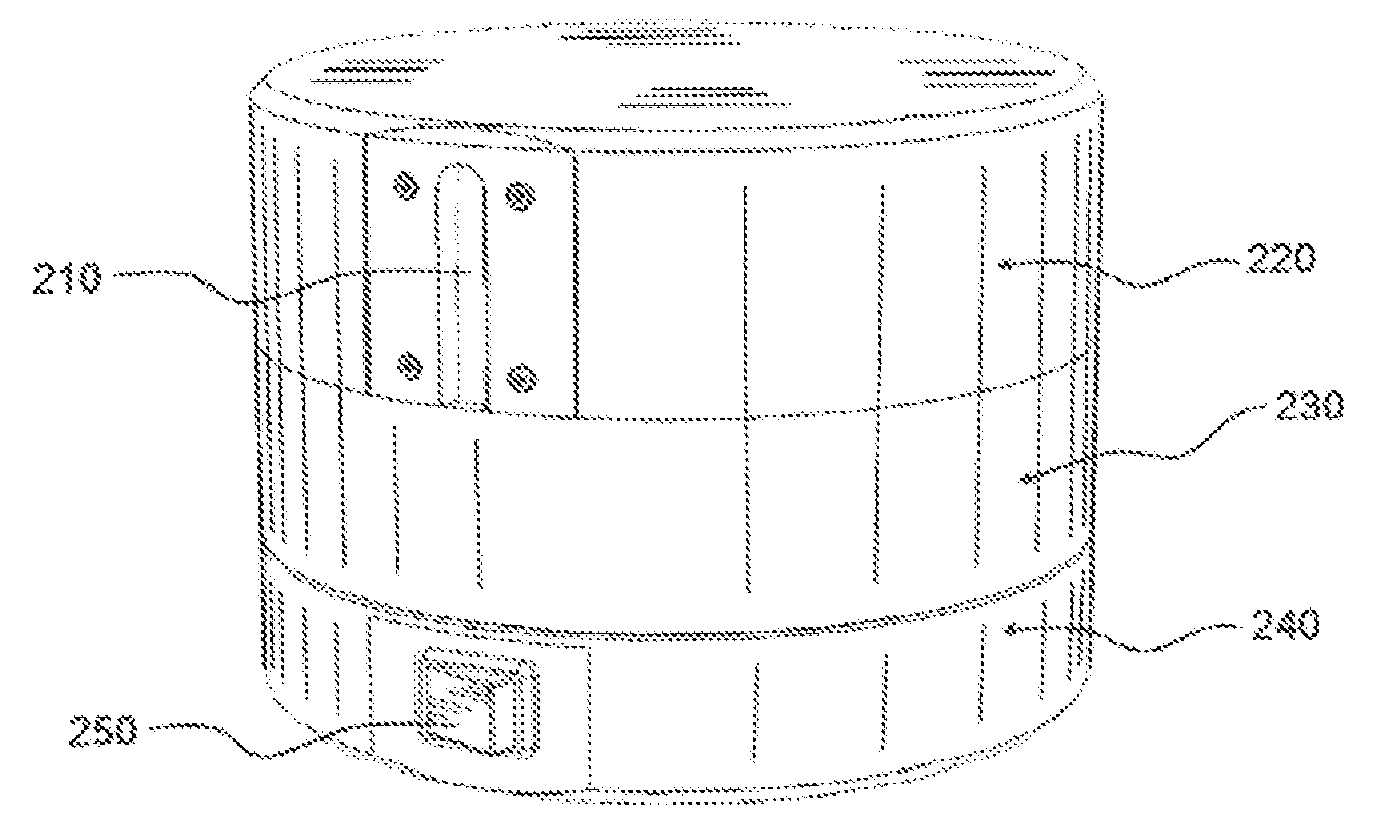
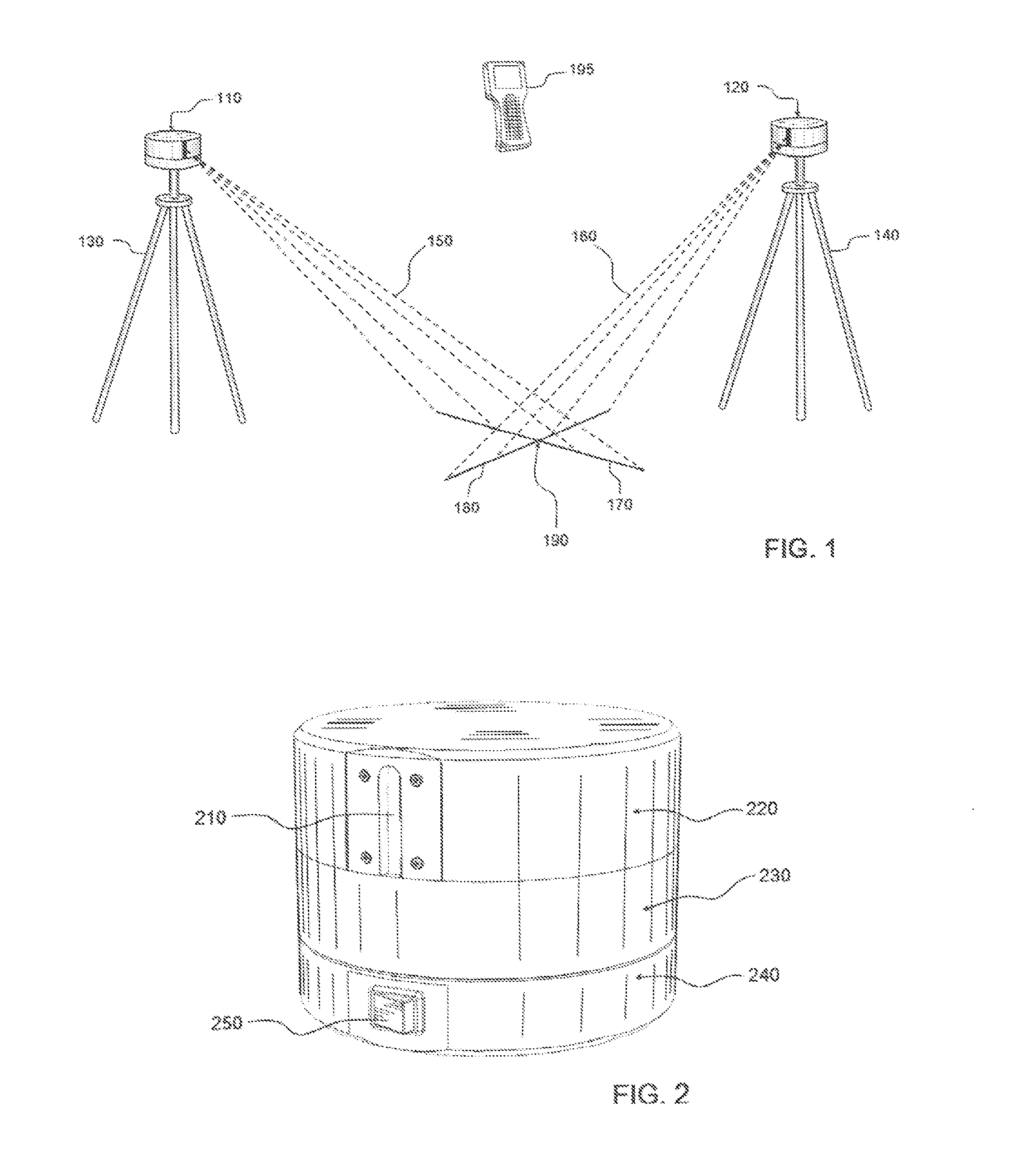
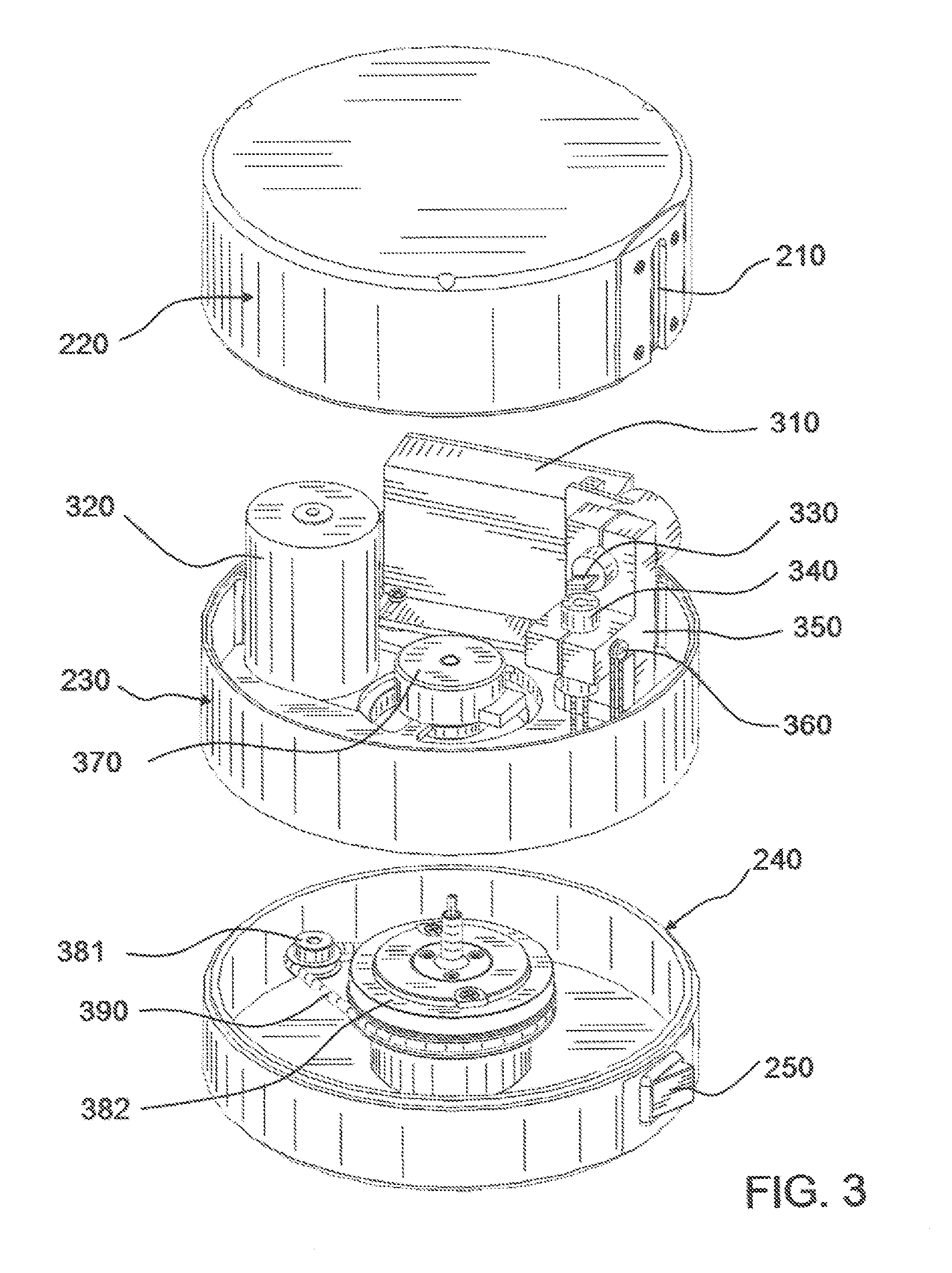
[0056]FIG. 1 is a pictorial view of one embodiment of the present invention illustrating the relative alignment of the individual First and Second Laser Projectors 110 and 120 according to one embodiment of the present invention, which are of significance to identify specified locations for surveying or construction. First and Second Laser Projectors 110 and 120 are placed on First and Second Tripods 130 and 140. First Laser Projector 110 projects First Laser Beam 150. Second Laser Projector 120 projects Second Laser Beam 160. First Laser Beam 150 is used to draw First Laser Line 170 and Second Laser Beam 160 is used to draw Second Laser Line 180. The intersecting location of First and Second Lase...


PUM


Abstract

A laser projection apparatus and method for identifying specified coordinates on varied surfaces. A controller directs two or more laser projectors to intersect laser lines at a specified location. The locations of the modules are identified by calculating a rotational angle and two or more known coordinates. Once the location of the modules is calculated, angle to angle intersection is used to identify additional locations. The user indicates with the controller which location is to be identified. The controller processes the calculations and commands the laser projectors to draw the intersecting laser lines at the specified location. The intersecting laser lines are actuated in a strobe effect to attract the user's attention to the position. This apparatus and method allows users to quickly and easily locate specified locations without needing to take individual measurements for the purposes of alignment, construction, verification and the like.

Description

BACKGROUND OF INVENTION[0001]1. Field of Invention[0002]The present invention generally relates to a method and device for identifying specified coordinates using two or more visible lasers. In more detail, the present invention relates to using two or more visible lasers lines and a method for calculating an angle to angle intersection to obtain the coordinates of predetermined locations.[0003]The art of large scale measurement and surveying involves the determination of unknown positions, or setting out of known coordinates using angle and distance measurements taken from one or more positions. In order to make these measurements, a surveying device or instrument frequently used is the type which is often called a total station. A total station is an electronic theodolite integrated with an electronic distance meter to read slope distances from the instrument to a particular point. The total station distance measuring instrument is capable of processing integrated distance and ang...

Claims


Application Information

Patent Timeline
Patent Type & Authority Applications(United States)
IPC IPC(8): G01B11/14G03B21/14G06F15/00
CPCG01B11/03
Inventor TRENT, KENNETHBELLISTON, BROCK TAYLOR
Owner TRENT KENNETH
Why Eureka
Try Eureka