Outboard motor

a technology for outboard motors and motors, applied in the direction of propulsive elements, water-acting propulsive elements, vessel construction, etc., can solve the problems of increasing manufacturing costs, complicated configuration of outboard motors, and limiting the use of outboard motors to relatively small motors

Active Publication Date: 2017-10-03
CAUDWELL MARINE LTD
View PDF9 Cites 4 Cited by
  • Summary
  • Abstract
  • Description
  • Claims
  • Application Information

AI Technical Summary

Problems solved by technology

The configurations of these motors, which include attachments to the boat's transom that allows the entire motor to pivot about its steering axis and about its trim / tilt axis is complicated—partly due to the multiplicity of pivot axes and partly because the entire engine needs to pivot about these axes—which can require large forces in the case of larger motors and which requires adequate space for the entire unit to pivot.
The forces required to pivot these units, as well as the forces exerted on the transom, limit the use of outboard motors to relatively small motors.
In many cases, stricter limitations on exhaust emissions are applied to inboard motors than to outboard motors and compliance with emissions limitations increase manufacturing costs—resulting in cost benefits from using outboard motors.
However, only smaller engines have conventionally been used in outboard configurations and the use of larger engines in outboard motors tends to be too complex, cumbersome and / or costly.
If a particular motor configuration requires deviation from a standard stern design offered by a hull manufacturer, the motor configuration can only be used if the hull manufacturer offers an alternative stern design (which increases tooling and / or manufacturing costs) or a standard hull needs to be modified after manufacture (also at considerable cost and / or detriment to hull quality).
Accordingly, there is significant resistance to marine motor configurations that require deviation from conventional, standard transom designs.

Method used


Image

  • Outboard motor
  • Outboard motor
  • Outboard motor

Examples


Embodiment Construction

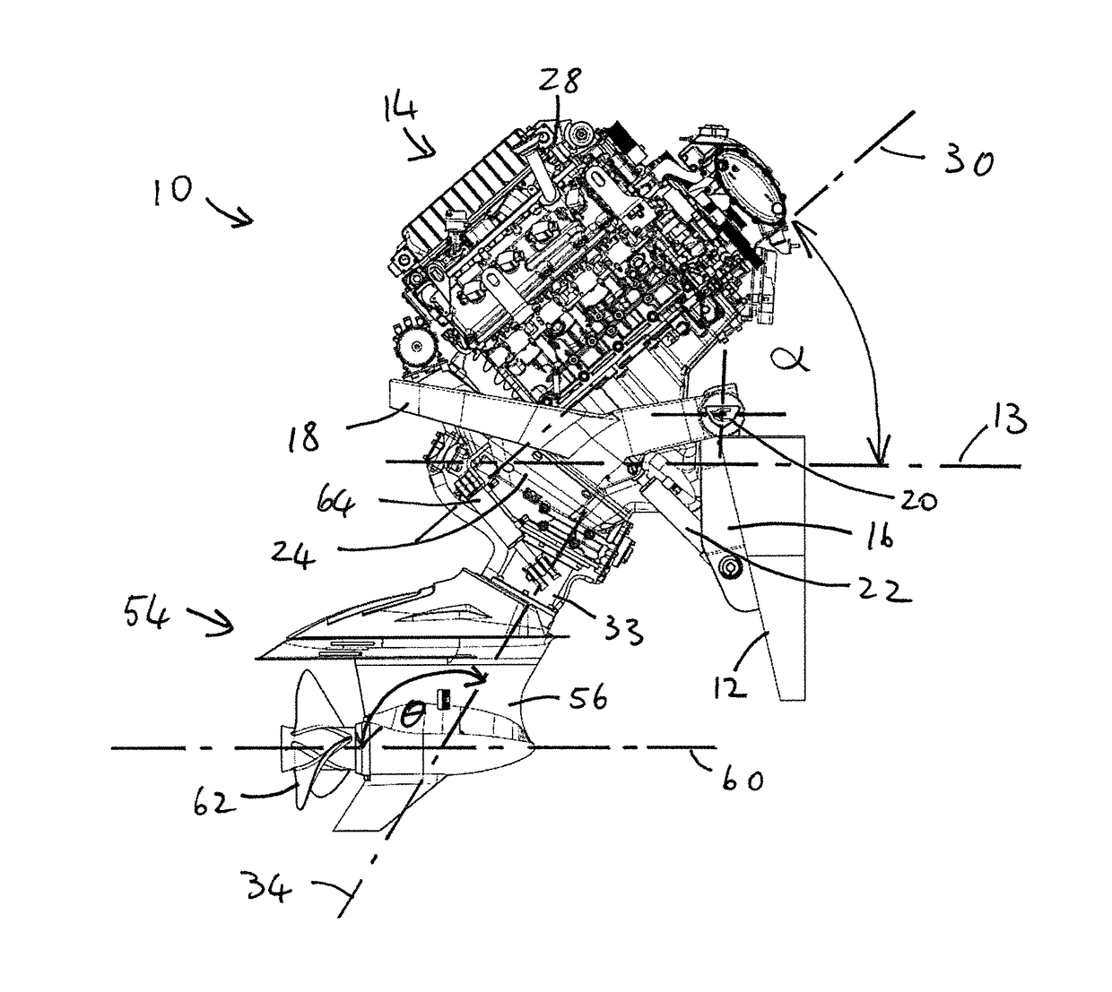
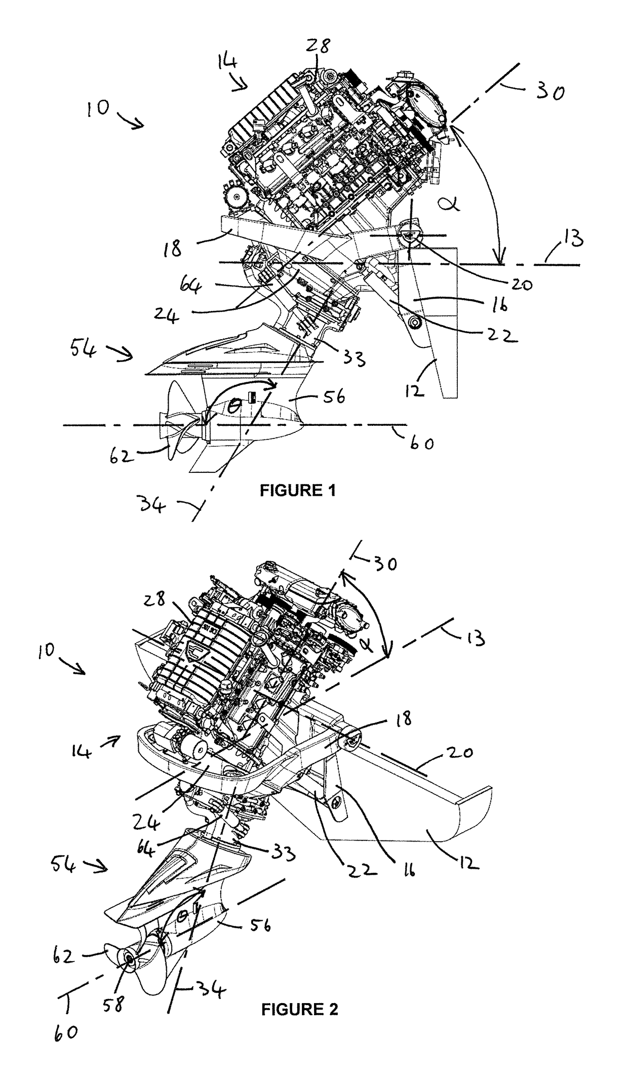
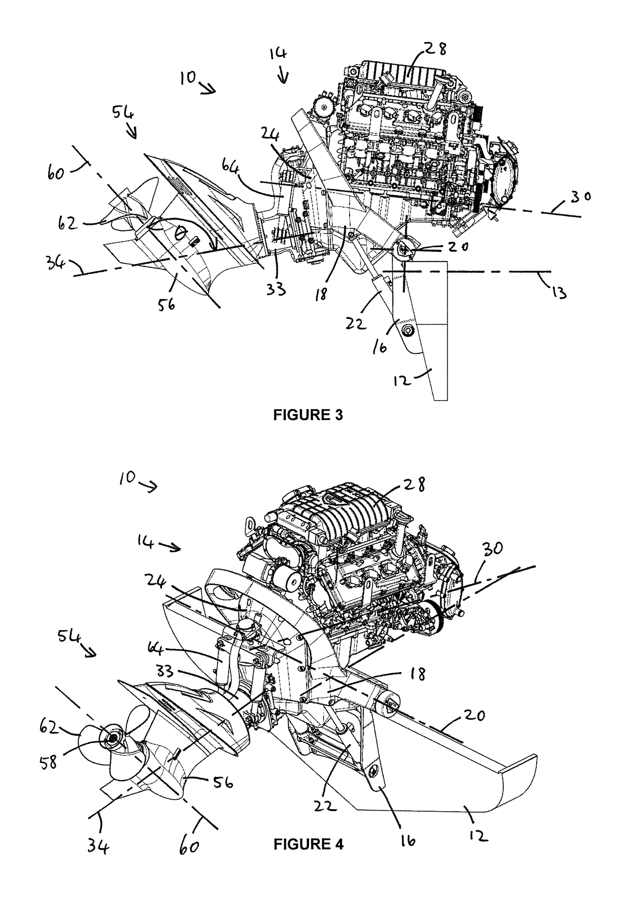
[0033]Referring to the drawings, an outboard motor according to the present invention is generally identified by reference numeral 10.

[0034]The outboard motor 10 is installed on the stern of a boat, e.g. it can be attached to a transom 12 of the boat and in the example, the transom is conventionally raked—e.g. at an angle of 10 degrees relative to vertical, although the invention can be used with various other attachments to the stern of a boat. The boat hull is not shown in the drawings, but the transom 12 is oriented transversely in relation to a longitudinal axis 13 of the boat. The outboard motor 10 includes an upper unit 14 that is attached to the transom 12 by a fixed mounting bracket 16 that is attached to the transom and a pivoting mounting bracket 18 that supports the upper unit 14. The pivoting mounting bracket 18 serves the purpose of a bracket, but also forms a unitary part with the crank casing of the engine 28 and supports the gearbox 24 (to which reference is made bel...


PUM


Abstract

An outboard motor includes a lower unit and an upper unit that is attachable to the stern of a boat, with the upper unit and lower unit configured to tilt together about a transverse tilt axis. The upper unit includes an engine, a transmission assembly and a drive shaft and the lower unit includes a lower unit housing and a propeller shaft that is connected to the drive shaft. The lower unit housing is configured to pivot relative to the upper unit, about a steering axis that extends coaxially with the drive shaft. The steering axis intersects the propeller axis at an obtuse angle.

Description

CROSS REFERENCE TO RELATED APPLICATIONS[0001]This application is a United States national phase of co-pending international patent application No. PCT / IB2015 / 054448, filed Dec. 17, 2015, which claims priority to Great Britain application No. GB1410476.4, filed Jun. 12, 2014, the entire disclosures of which are incorporated by reference in their entirety.FIELD OF THE INVENTION[0002]This invention relates to drives for propulsion of marine vessels (boats). In particular, the invention relates to outboard motors.BACKGROUND TO THE INVENTION[0003]A conventional outboard motor is a self-contained unit that can be fitted on the transom of a boat and that includes an engine, transmission and propeller (or jet drive). The entire unit can pivot relative to the transom about a vertical steering axis, to control the direction of thrust from the propeller—and thus steer the boat. The entire unit can also be pivoted relative to the transom about a transverse, horizontal trim / tilt axis, to trim th...

Claims


Application Information

Patent Timeline
Patent Type & Authority Patents(United States)
IPC IPC(8): B63H20/10B63H23/30B63H23/34B63H20/16B63H20/20
CPCB63H20/16B63H20/10B63H20/20B63H23/30B63H23/34B63B2749/00
Inventor BEACHY HEAD, MICHAEL ALAN
Owner CAUDWELL MARINE LTD
Why Eureka
Try Eureka