
Tire-pressure monitoring device

a monitoring device and tire pressure technology, applied in the direction of tire measurement, vehicle components, transportation and packaging, etc., can solve the problems of inability to distinguish whether, count-up of a wheel-speed pulse, and inability to acquire a sufficient degree of wheel location discrimination, etc., to achieve the effect of easy and accurate judgmen

Active Publication Date: 2017-10-10
TOYOTA JIDOSHA KK
View PDF9 Cites 1 Cited by
  • Summary
  • Abstract
  • Description
  • Claims
  • Application Information

AI Technical Summary

Benefits of technology

[0010]The objective of the present invention has been made in order to cope with the above-mentioned issue, and it is in shortening the time period for a wheel location discrimination treatment.
[0032]Therefore, even when the vehicle has stopped during the discrimination of the wheel location, a count treatment of the pulse signal can be continued using a proper count value. For this reason, the pulse count value acquired before the vehicle stops by the pulse count means can be used effectively. As a result, in accordance with the present invention, the time period required for the wheel location discrimination treatment can be shortened.
[0035]In the one aspect of the present invention, since it is judged whether the vehicle speed is within the minute low speed range using the count value per unit time of the pulse signal of all the wheel-speed sensors, it can be easily and accurately judged whether the vehicle speed is within the minute low speed range. Moreover, the hysteresis (dead band) of the vehicle speed used for the evaluation can be set up properly.

Problems solved by technology

Therefore, it cannot be distinguished whether the cause of count-up of a wheel-speed pulse is due to disturbance, such as an oscillation, or the fact that the wheel has been rotated actually.
For this reason, the device proposed in the Patent Document 1 (PTL1) cannot properly correct the count value of a wheel-speed pulse, and cannot acquire a sufficient accuracy in wheel location discrimination.
For this reason, it becomes impossible to use the count value of the wheel-speed pulse sampled before the vehicle stopped, and the time period for completing the wheel location discrimination treatment will become long.

Method used


Image

  • Tire-pressure monitoring device
  • Tire-pressure monitoring device
  • Tire-pressure monitoring device

Examples


Embodiment Construction

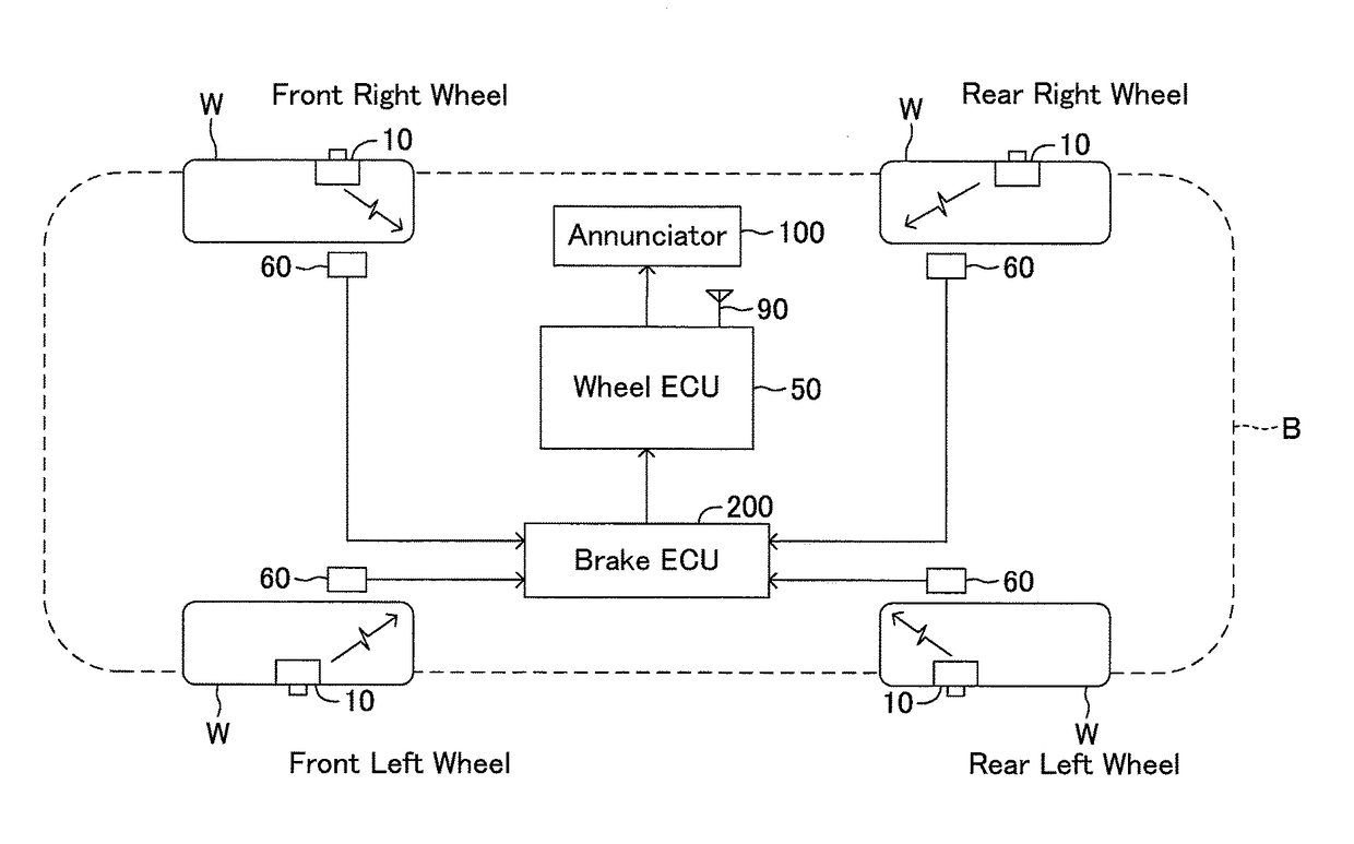
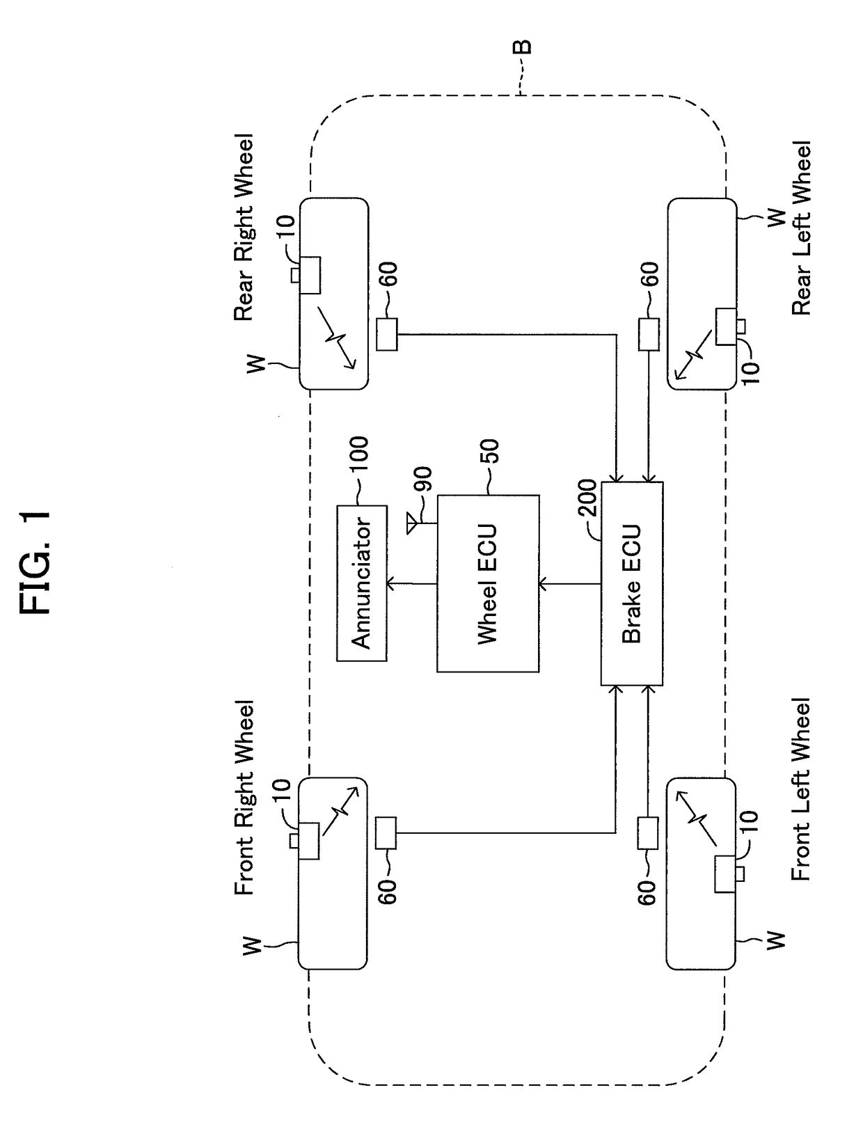
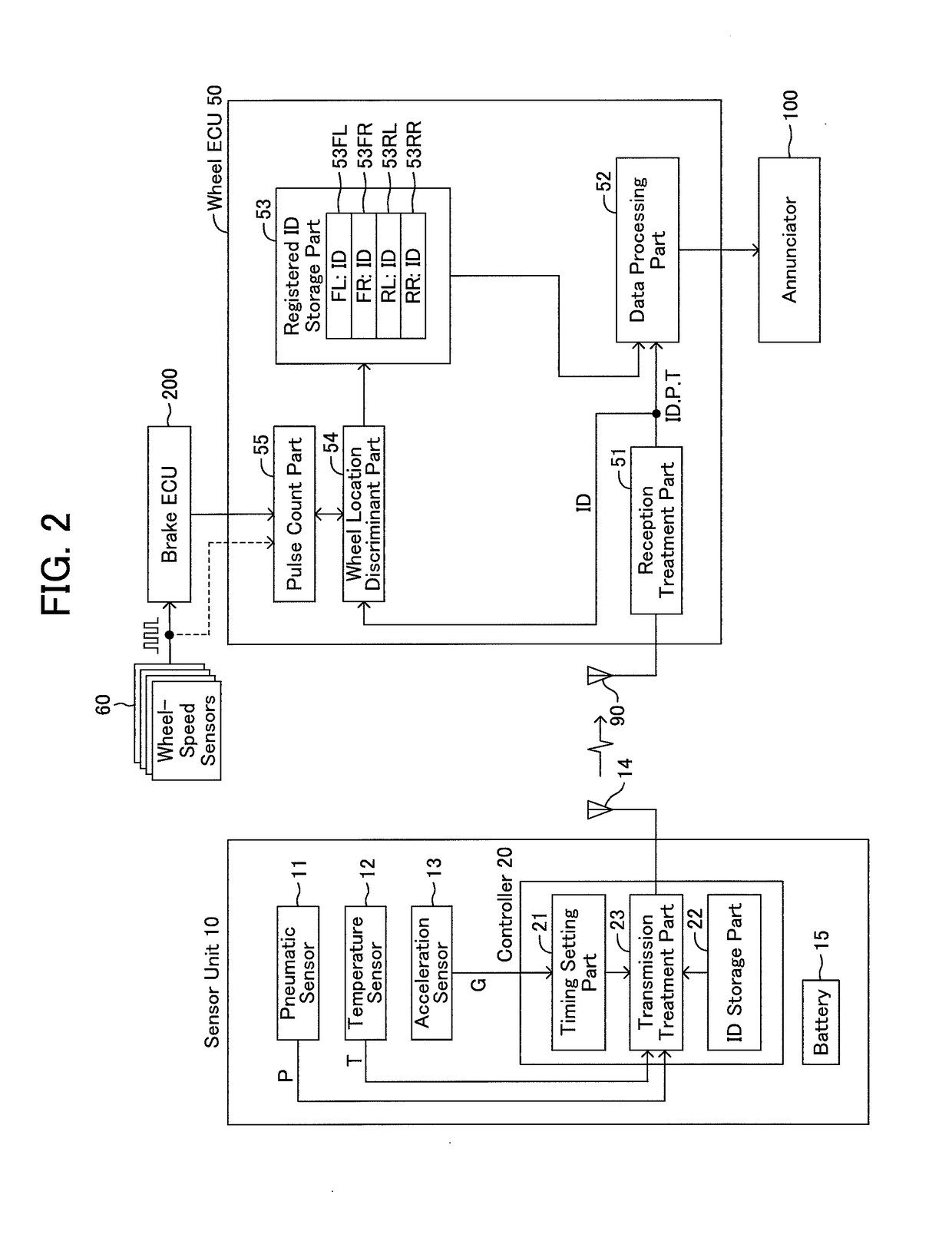
[0047]Hereafter, a tire-pressure monitoring device according to one embodiment of the present invention will be explained using drawings. FIG. 1 is a diagram for showing the schematic configuration of the tire-pressure monitoring device of a vehicle. The tire-pressure monitoring device is a device for informing a driver of an air pressure information of a tire, and comprises tire-pressure sensor units 10 (hereafter, referred to as sensor units 10) which is fixed to respective wheels W, a wheel state information process unit 50 (hereafter, referred to as a wheel ECU 50) fixed to a vehicle body B and an annunciator 100. FIG. 2 is a functional block diagram in a sensor unit 10 and a wheel ECU 50. Since all the sensor units 10 disposed at respective wheels W serve the same function, one of them is shown in FIG. 2.

[0048]The sensor unit 10 is attached to a tire air injection valve of a wheel W. The sensor unit 10 comprises a pneumatic sensor 11, a temperature sensor 12, an acceleration se...


PUM


Abstract

A pulse count part acquires the minimum value among the numbers of pulse signals outputted by respective wheel-speed sensors during a wheel speed is within a minute low speed range. The pulse count part sets said minimum value as the numbers of the pulse signals of respective wheel-speed sensors during the wheel speed is within the minute low speed range, when the wheel speed increases out of said minute low speed range. Thereby, even when a vehicle stops in the middle of a wheel location discrimination treatment, a wheel location discrimination treatment can be continued using a proper pulse count value.

Description

TECHNICAL FIELD[0001]The present invention relates to a tire-pressure monitoring device comprising wheel sensors fixed to respective wheels and a vehicle body side device fixed to a vehicle body, wherein the vehicle body side device performs a notification process according to a tire pressure by transmitting a tire-pressure information which represents a tire pressure from each wheel sensor to the vehicle body side device as a radio signal.BACKGROUND ART[0002]Conventionally, a tire-pressure monitoring device which informs a driver of a tire-pressure information has been known. A tire-pressure monitoring device comprises tire-pressure sensor units (referred to as wheel sensors) for detecting a tire pressure for respective wheels, and is configured to transmit a tire-pressure information as a radio signal from this wheel sensor and receive this radio signal by a vehicle body side device to acquire the tire-pressure information. When judged that the tire pressure has been reduced based...

Claims


Application Information

Patent Timeline
Patent Type & Authority Patents(United States)
IPC IPC(8): B60C23/04
CPCB60C23/0433B60C23/0489B60C23/0416B60C23/0488
Inventor TAKI, YUJI
Owner TOYOTA JIDOSHA KK
Learn More