Wind power generation system and operating method thereof

a wind power generation and wind power technology, applied in the direction of electric generator control, machine/engine, dynamo-electric converter control, etc., can solve the problems of system power generation, wind turbine cannot resume power generation immediately, and conventional wind power generation system has another problem, so as to reduce the amount of power generated by the wind power generation system and shorten the power generation operation

Active Publication Date: 2009-08-04
HITACHI LTD
View PDF5 Cites 53 Cited by
  • Summary
  • Abstract
  • Description
  • Claims
  • Application Information

AI Technical Summary

Benefits of technology

[0009]One object of this invention is to provide a wind power generation system which can shorten the time period from the elimination of the failure in the power grid till the wind turbine resumes its power generating operation.
[0010]Another object of this invention is to provide a wind power generation system comprising an abnormality detecting unit for detecting an abnormal condition occurring in the wind power generation system or a power grid with which the wind power generation system is connected, a first pitch controlling unit for controlling the blade pitch of the rotor of the wind turbine installed in the wind power generation system when the abnormal condition is not detected, and a second pitch controlling unit for controlling the blade pitch when the abnormal condition is detected, wherein the second pitch controlling unit serves to keep the rotational speed of the rotor within the range for which the wind power generation system can perform power generating operation.
[0012]According to this invention, the time period from the elimination of the failure in the power grid till the wind turbine resumes its power generating operation can be shortened. Consequently, the amount of power generated by the wind power generation system can be increased.

Problems solved by technology

Thus, with conventional wind power generation systems, the wind turbine cannot resume its power generating operation immediately after the elimination of the failure since some time period is required between the time of failure detection and the time of resuming power generation before the wind turbine reaches a rotational speed suitable for power generation.
As a result, the conventional wind power generation system has suffered a problem that the system cannot generate power for a relatively long time from the recovery of the failed power grid till the wind turbine reaches the rotational speed suitable for power generation.
In addition to this, the conventional wind power generation system has another problem.
Namely, in a power grid whose power generation owes to a large extent to a wind power generation system connected to the grid, the delay in the restart of the wind power generation system after the elimination of failure amounts to the inability of a large-scale power generating system included in the grid for a long time.
This may collapses the balance of power demand and supply, sometimes causing large fluctuations of grid frequency and voltage and ultimately causing a power failure.

Method used


Image

  • Wind power generation system and operating method thereof
  • Wind power generation system and operating method thereof
  • Wind power generation system and operating method thereof

Examples


embodiment 1

[0041]The configurations and operations of the wind power generation systems according to an embodiment of the present invention will be described with reference to FIGS. 1 through 16 of the attached drawings.

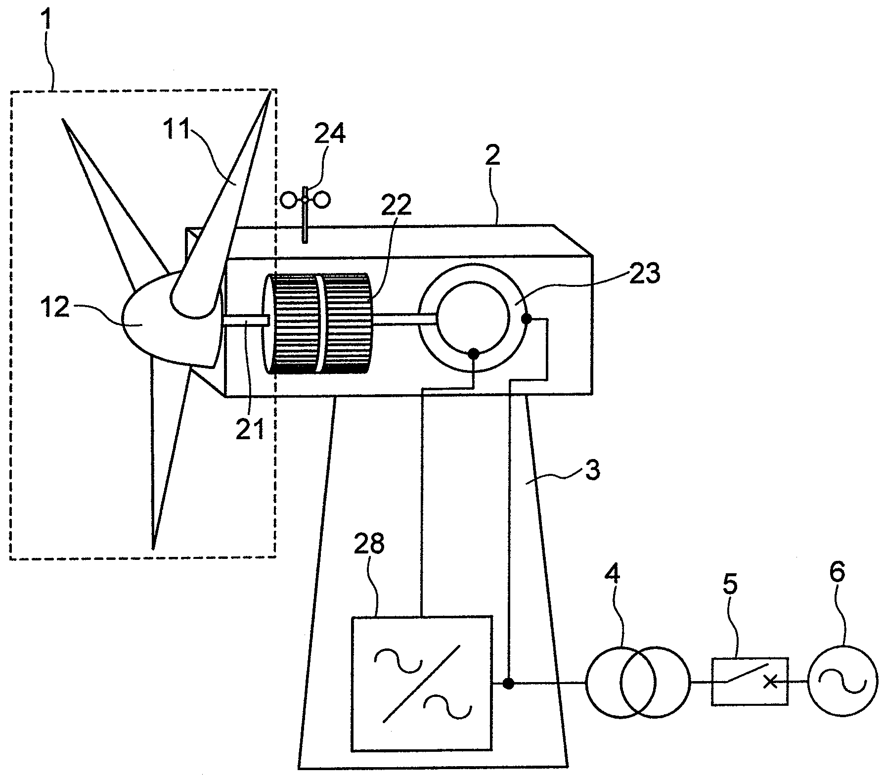
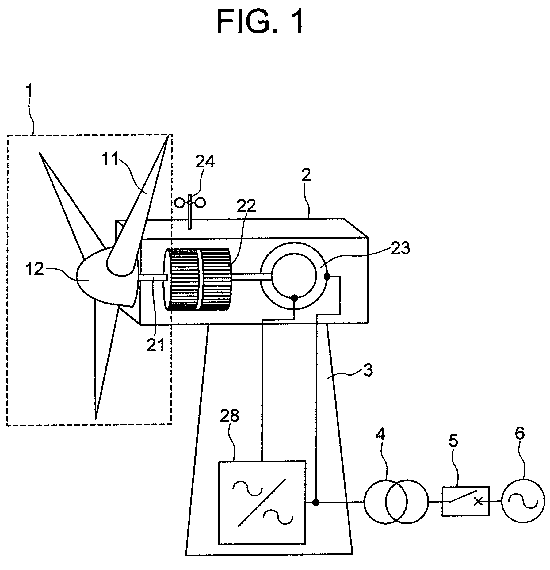
[0042]FIG. 1 schematically shows the overall configuration of a wind power generation system as a first embodiment of this invention. In FIG. 1, the wind power generation system has blades 11 driven by the wind so that the wind energy is turned into rotational energy. The rotational energy in turn causes a hub 12, to which the blades 11 are attached, to rotate. The rotary assembly consisting of the blades 11 and the hub 12 is referred to as a rotor 1. The rotation of the rotor 1 is transferred to an acceleration gear 22 via a shaft 21. The acceleration gear 22 converts the rotational speed of the rotor 1 to a rotational speed suitable for the power generating operation of a generator. In FIG. 1, a doubly fed induction generator 23 is shown as such a generator. The stator windin...

embodiment 2

[0082]The second embodiment of this invention will now be described. In this embodiment, the pitch control procedure is changed in accordance with the rate of decrease in the grid voltage.

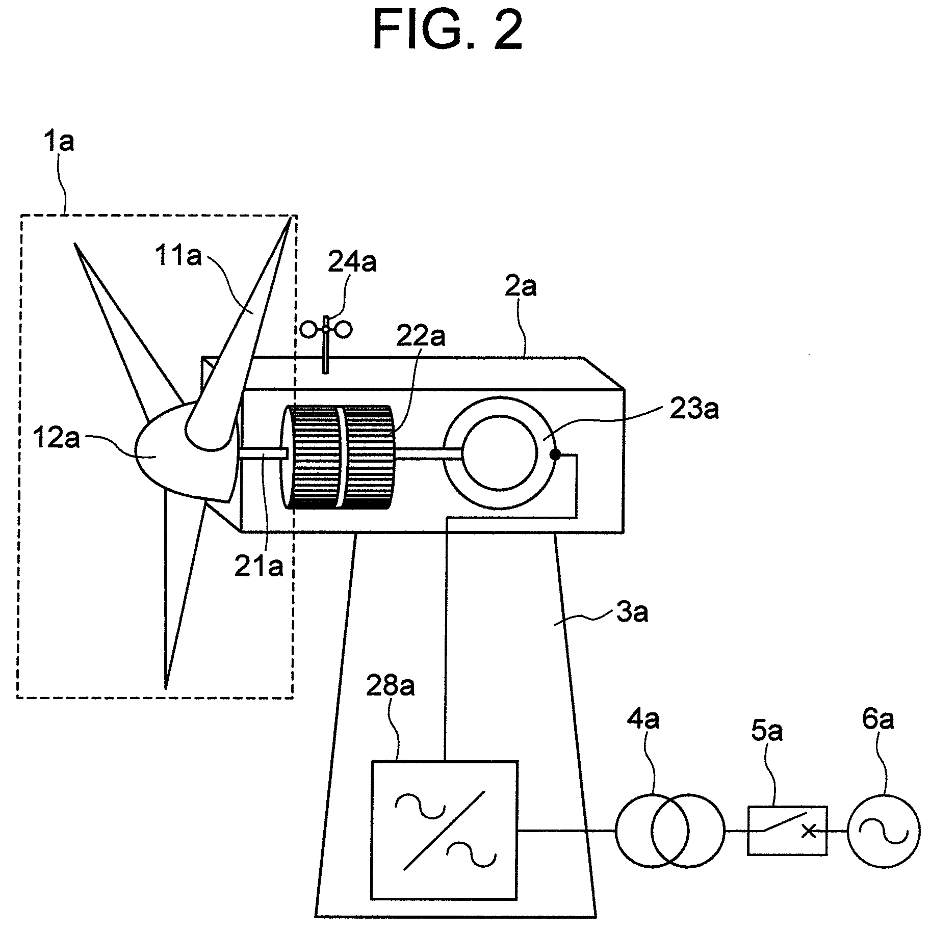
[0083]This embodiment can be applied to such a wind power generation system as shown in FIGS. 1 and 2, which has a power converter 28 as a constituent part and which can control the generated power. Since the pitch control and the control of the generated power in the normal power generating operation according to this second embodiment are similar to those described with the foregoing first embodiment of this invention, their description is omitted here.

[0084]Described below is a control procedure used in a wind power generation system when a low voltage event occurs in a power grid connected with the system. In a power distribution grid, a short-time fall of the grid voltage may be caused due to, for example, thunderbolts, the contacts of power transmission line with trees, the failure of loads, ...

embodiment 3

[0098]The third embodiment of this invention will now be described with reference to FIGS. 21, 22, 23 and 24. FIG. 21 schematically shows the configuration of a wind power generation system using a permanent magnet generator, according to the third embodiment of the invention. The control section of the system consists mainly of a system controller 25e for controlling the entire system, and a power converter controller 26e for controlling a power converter 28e. The system controller 25e calculates power command and pitch command for blades 11e on the basis of the wind velocity measured by an anemometer 24e and the rotational speed ω [rad / sec] of the rotor 1.

[0099]The power generated by the wind power generation system is controlled by the power converter 28e. The power converter 28e consists mainly of a generator-side power converter 281e, a grid-side power converter 283e, and an intermediate (smoothing) capacitor 282e. The generator-side power converter 281e and the grid-side power...


PUM


Abstract

A wind power generation system wherein procedure for controlling the blade pitch is changed in accordance with the rate of decrease in the amplitude of the grid voltage, and when over current occurs in the grid-side power converter, the grid-side power converter is brought into the gate-blocked condition whereas the generator-side power converter continues its operation.

Description

CROSS-REFERENCE TO RELATED APPLICATION[0001]The present application relates to subject matters described in a co-pending patent applications Ser. No. 11 / 769,753 filed on Jun. 28, 2007 entitled “VARIABLE SPEED WIND POWER GENERATION SYSTEM”, Ser. No. 11 / 751,742 filed on May 22, 2007 entitled “WIND POWER GENERATION APPARATUS, WIND POWER GENERATION SYSTEM AND POWER SYSTEM CONTROL APPARATUS”, and Ser. No. 11 / 954,453 filed on Dec. 12, 2007 entitled “WIND POWER GENERATION SYSTEM” every which by Masaya Ichinose, et al. and assigned to the assignees of the present application. The disclosures of these co-pending applications are incorporated herein by reference.BACKGROUND OF THE INVENTION[0002]This invention relates to a power generation system connected with a power distribution grid, and more particularly to a wind power generation system connected with a power grid.[0003]When the voltage or frequency of a power grid becomes abnormal, the wind power generation system connected with the pow...

Claims


Application Information

Patent Timeline
Patent Type & Authority Patents(United States)
IPC IPC(8): H02P9/00
CPCF03D7/0224F03D7/0284F03D9/003Y02E10/722F05B2270/337Y02E10/723Y02E10/725F05B2270/101F03D9/255Y02E10/72
Inventor OOHARA, SHINYAICHINOSE, MASAYAFUTAMI, MOTOOSODEYAMA, TADASHI
Owner HITACHI LTD
Why Eureka
Try Eureka