[0005]The present invention has been devised in view of the above-described matter, and an object of the present invention is to provide a passenger protection device of a vehicle which can compatibly achieve preventing of the breakage of the guide portion for the curtain airbag which is provided at the pillar trim and ensuring of the safety of the passenger hitting against a portion of the pillar trim which corresponds to the guide portion.
[0007]According to the present invention, even if the inflation pressure of the curtain airbag is large, the inflation pressure acting on the guide portion can be suppressed (reduced) by the inflation suppression portion, so that the breakage of the guide portion can be prevented. Further, since the inflation pressure acting on the guide portion can be suppressed (reduced), the rigidity of the guide portion can be maintained to be relatively small, which is preferable in ensuring the safety of the passenger hitting against the guide portion in the vehicle collision. Moreover, since the curtain airbag includes the upper gas-flow passage extending in the vehicle longitudinal direction, the inflating gas from the inflator can be effectively distributed in the vehicle longitudinal direction inside the curtain airbag.
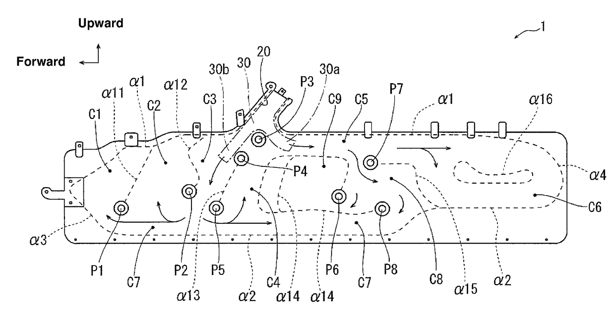
[0008]According to an embodiment of the present invention, the inflation suppression portion is arranged at a front portion of the upper gas-flow passage, and the curtain airbag comprises a cell which is formed at a position located in front of the inflation suppression portion, the cell being configured such that an upper-side portion thereof is closed and the inflating gas flows in from a lower-side portion thereof when the curtain airbag is inflated. Thereby, even if the inflation suppression portion is provided, it can be properly prevented that the inflation suppression portion blocks smooth gas flowing inside the curtain airbag.
[0009]According to another embodiment of the present invention, the curtain airbag comprises an inflation portion which is positioned located below the inflation suppression portion and extends vertically along the pillar trim when the curtain airbag is inflated, the inflation portion being configured such that the inflating gas flows in from a lower-side portion thereof. Thereby, it can be prevented or suppressed that the vicinity of the inflation suppression portion is inflated (the inflation pressure becomes large) unnecessarily by the inflation from the lower-side portion.
[0010]According to another embodiment of the present invention, an inner bag is provided at the gas inlet portion of the curtain airbag, the inner bag branches at a position located above said inflation suppression portion into two or more branch flow passages which connect to gas-flow passages, and each of the branch flow passages extend downward to a position which overlaps with the inflation suppression portion. Thereby, it can be prevented that the vicinity of the inflation suppression portion is inflated (the inflation pressure becomes large) unnecessarily by using the inner bag, providing smooth gas introduction into the curtain airbag.
[0013]According to another embodiment of the present invention, the inflation suppression portion is reinforced by two-sheet overlapped cloth-made reinforcing materials, and the two-sheet cloth-made reinforcing materials are attached to the curtain airbag such that respective fiber directions (fine-line directions) of the two-sheet cloth-made reinforcing materials attached cross each other. Thereby, the strength of the inflation suppression portion is ensured surely, which is preferable in preventing a situation in which a portion of the curtain airbag where the inflation suppression portion is provided gets damaged.

