Plasma film-forming apparatus and plasma film-forming method

a technology of plasma film and forming apparatus, which is applied in the direction of plasma technique, chemical vapor deposition coating, coating, etc., can solve the problems of decreased apparatus availability, increased cost, and inability to appropriately generate plasma in the plasma generation region to affect the film formation on the substra

Inactive Publication Date: 2010-02-09
TOKYO ELECTRON LTD
View PDF11 Cites 121 Cited by
  • Summary
  • Abstract
  • Description
  • Claims
  • Application Information

AI Technical Summary

Benefits of technology

[0010]According to the present invention, the plasma excitation gas can be supplied from the lower side toward the region on the high frequency wave supply unit side where plasma is generated in the processing container. This configuration can prevent the plasma excitation gas before supplied into the processing container from turning into plasma due to the high frequency wave from above from the high frequency wave supply unit. As a result, it is possible to prevent charged particles from breaking the portion near the plasma excitation gas supply port and the inside of the supply path leading thereto. Further, a sufficient amount of plasma excitation gas can be supplied to the region on the high frequency wave supply unit side, so that a film is appropriately formed on the substrate on the mounting unit.
[0015]The structure may have a gas supply pipe leading to a supply source of the source gas arranged in a lattice form in a plan view, a plurality of the source gas supply ports may be formed in the gas supply pipe, the gas supply pipe may also lead to a supply source of the plasma excitation gas, and the source gas supply port may have a function as the plasma excitation gas supply port. In this case, the supply system of the plasma excitation gas supplied from the plasma excitation gas supply port and the supply system of the source gas are used in a combined manner, so that the supply systems of the gasses can be simplified.
[0019]According to the present invention, film formation within a substrate can be performed uniformly and appropriately.

Problems solved by technology

Accordingly, in the above-described plasma film forming apparatus, there is a need to frequently perform maintenance and change of parts, bringing about a decrease in apparatus availability and an increase in cost.
Further, as a result of the plasma excitation gas turning into plasma in the path and so on, the amount of the plasma excitation gas supplied to the plasma generation region becomes insufficient, so that plasma may not be appropriately generated in the plasma generation region to affect the film formation on the substrate.

Method used


Image

  • Plasma film-forming apparatus and plasma film-forming method
  • Plasma film-forming apparatus and plasma film-forming method
  • Plasma film-forming apparatus and plasma film-forming method

Examples


Embodiment Construction

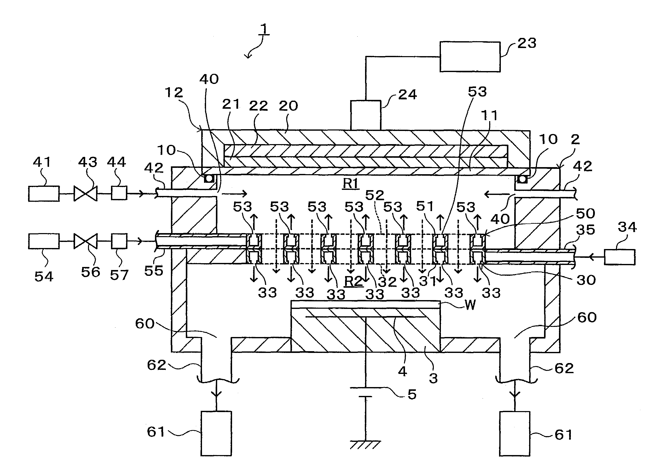
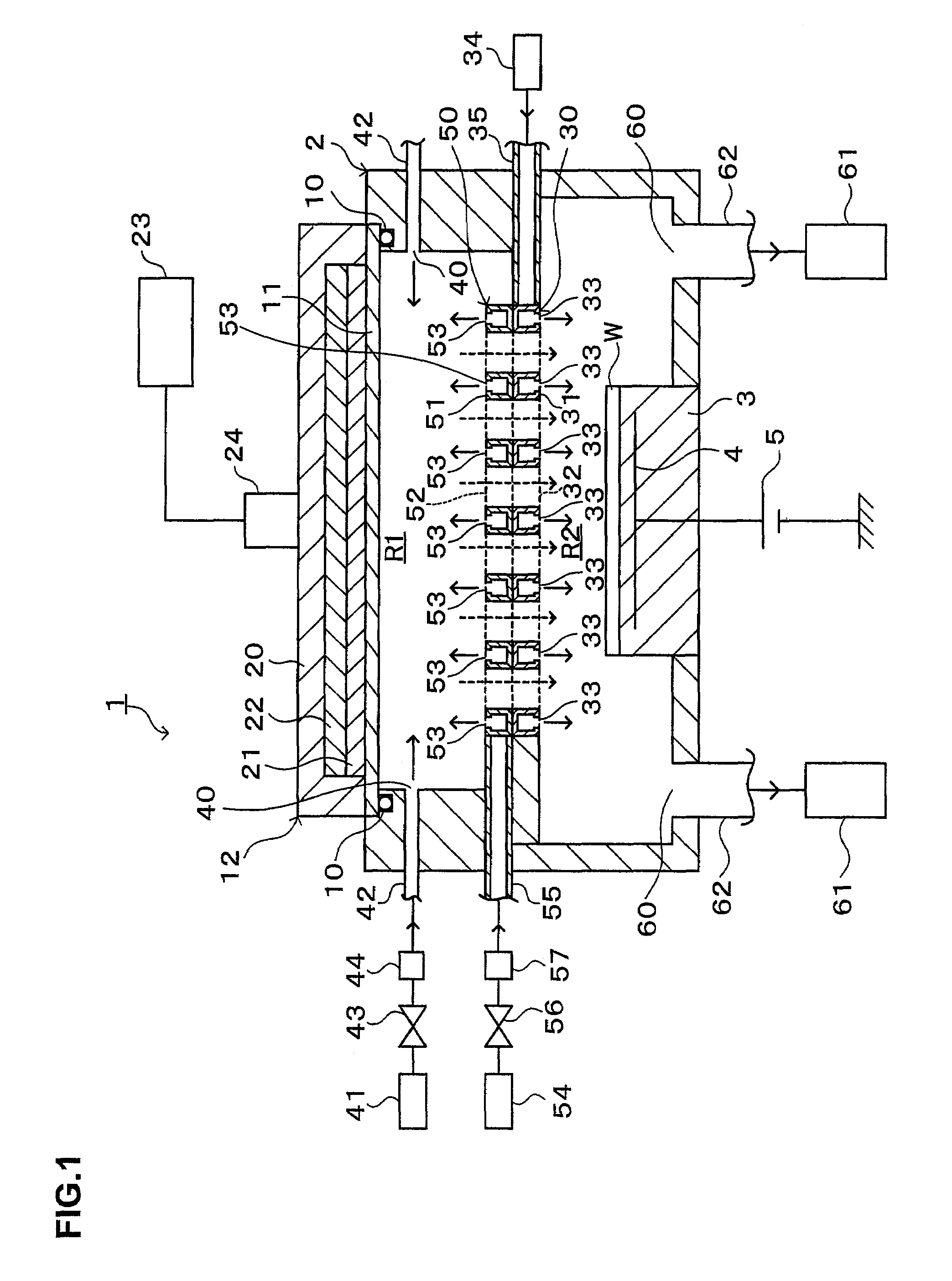
[0041]Hereinafter, a preferred embodiment of the present invention will be described. FIG. 1 schematically shows the appearance of a longitudinal section of a plasma film forming apparatus 1 according to the embodiment of the present invention. This plasma film forming apparatus 1 is a CVD (chemical vapor deposition) apparatus for generating plasma using a radial line slot antenna.

[0042]The plasma film forming apparatus 1 includes a processing container 2, for example, in a bottomed cylindrical shape with a top face open. The processing container 2 is made of, for example, an aluminum alloy. The processing container 2 is grounded. At an almost central portion of the bottom portion of the processing container 2, a mounting table 3 is provided as a mounting unit for mounting, for example, a substrate W thereon.

[0043]The mounting table 3 incorporates, for example, a electrode plate 4, and the electrode plate 4 is connected to a direct-current power supply 5 provided outside the process...


PUM

PropertyMeasurementUnit
frequencyaaaaaaaaaa
pressureaaaaaaaaaa
frequencyaaaaaaaaaa

Abstract

The present invention ensures a uniform concentration of a plasma excitation gas supplied to a plasma generation region while preventing the plasma excitation gas from turning into plasma before supply. In a plasma film forming apparatus for forming a film on a substrate using plasma, a flat-plate structure partitioning the inside of a processing container into two, upper and lower, regions is disposed between a high frequency wave supply unit and a substrate mounting unit in the processing container. The plasma excitation gas is supplied into the processing container from the lower side toward the region on the high frequency wave supply unit side, and the structure is formed with a source gas supply port for supplying a source gas for film formation in the region on the mounting unit side and an opening for allowing plasma generated in the region on the high frequency wave supply unit side to pass to the region on the mounting unit side.

Description

TECHNICAL FIELD[0001]The present invention relates to a plasma film forming apparatus and a plasma film forming method each for forming a film on a substrate.BACKGROUND ART[0002]In a manufacturing process of a semiconductor device and a liquid crystal display device, for example, film forming processing is performed for forming a conductive film and an insulating film on the surface of a substrate. For the film forming processing, for example, plasma film forming processing is used for forming a film on the substrate using plasma.[0003]The above plasma film forming processing is generally performed in a plasma film forming apparatus, for which a plasma film forming apparatus has been conventionally employed which generates plasma through use of a microwave electric field to form a film. With the plasma film forming apparatus using a microwave, the film forming processing on the substrate can be efficiently performed in a short time through use of high density plasma.[0004]The above-...

Claims


Application Information

Patent Timeline
Patent Type & Authority Patents(United States)
IPC IPC(8): C23C16/00C23C16/511C23C16/455H01J37/32H01L21/205H01L21/31
CPCC23C16/45565C23C16/511H01J37/3244H01J37/32192C23C16/52
Inventor ISHIKAWA, HIRAKU
Owner TOKYO ELECTRON LTD
Why Eureka
Try Eureka