Seat for hip shaking

a hip shaking and seat technology, applied in the field of seats for hip shaking, can solve the problems of less efficiency of the device, certain design limitations of the conventional body vibration machine,

Active Publication Date: 2017-10-17
TECVIEW GRP CO LTD
View PDF38 Cites 24 Cited by
  • Summary
  • Abstract
  • Description
  • Claims
  • Application Information

AI Technical Summary

Benefits of technology

[0004]Therefore it is a primary object of the present invention to provide a seat for hip shaking by which users can ...

Problems solved by technology

Yet the conventional body vibration machine has cert...

Method used


Image

  • Seat for hip shaking
  • Seat for hip shaking
  • Seat for hip shaking

Examples


Embodiment Construction

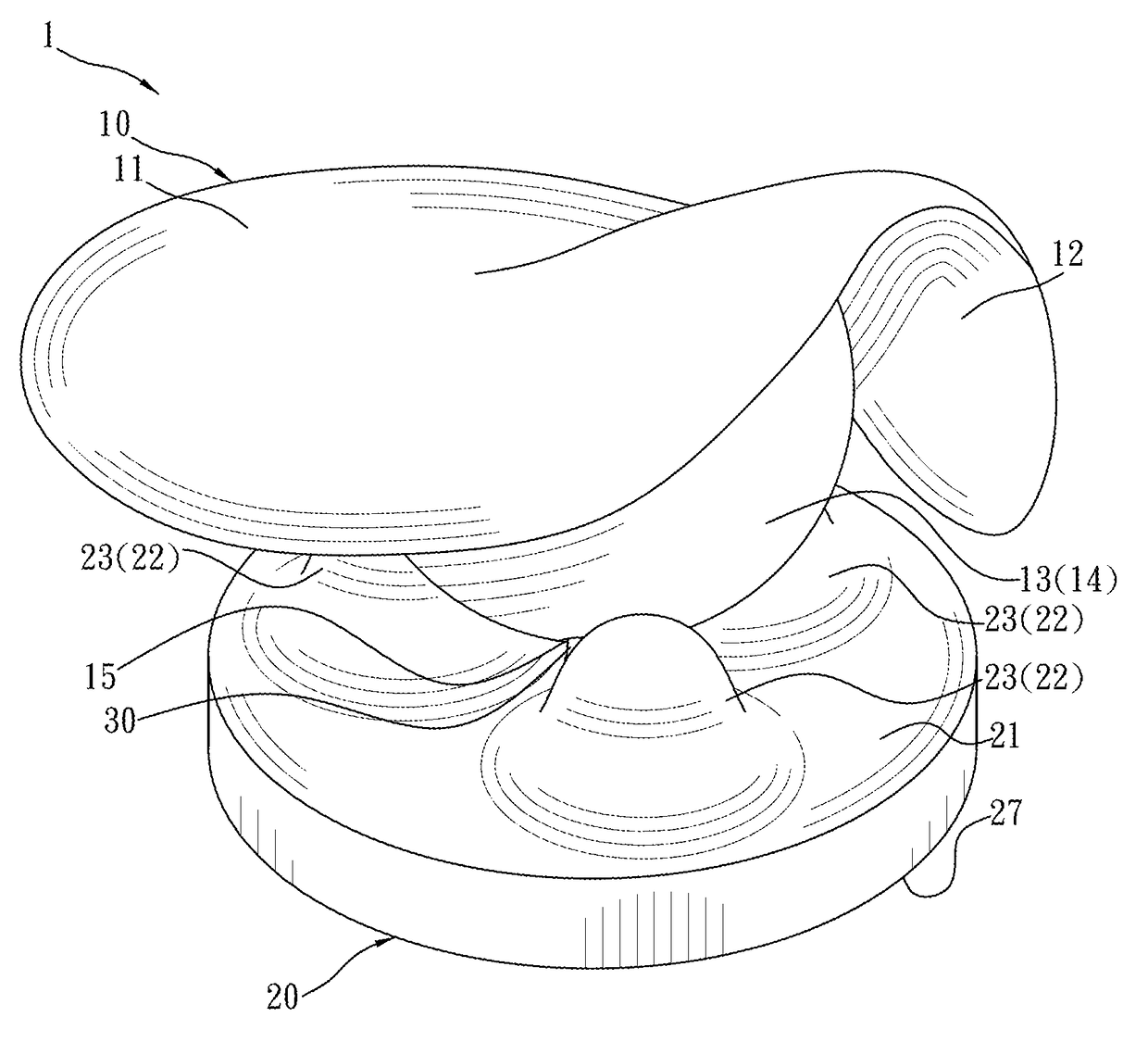
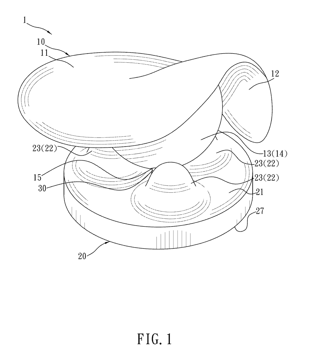
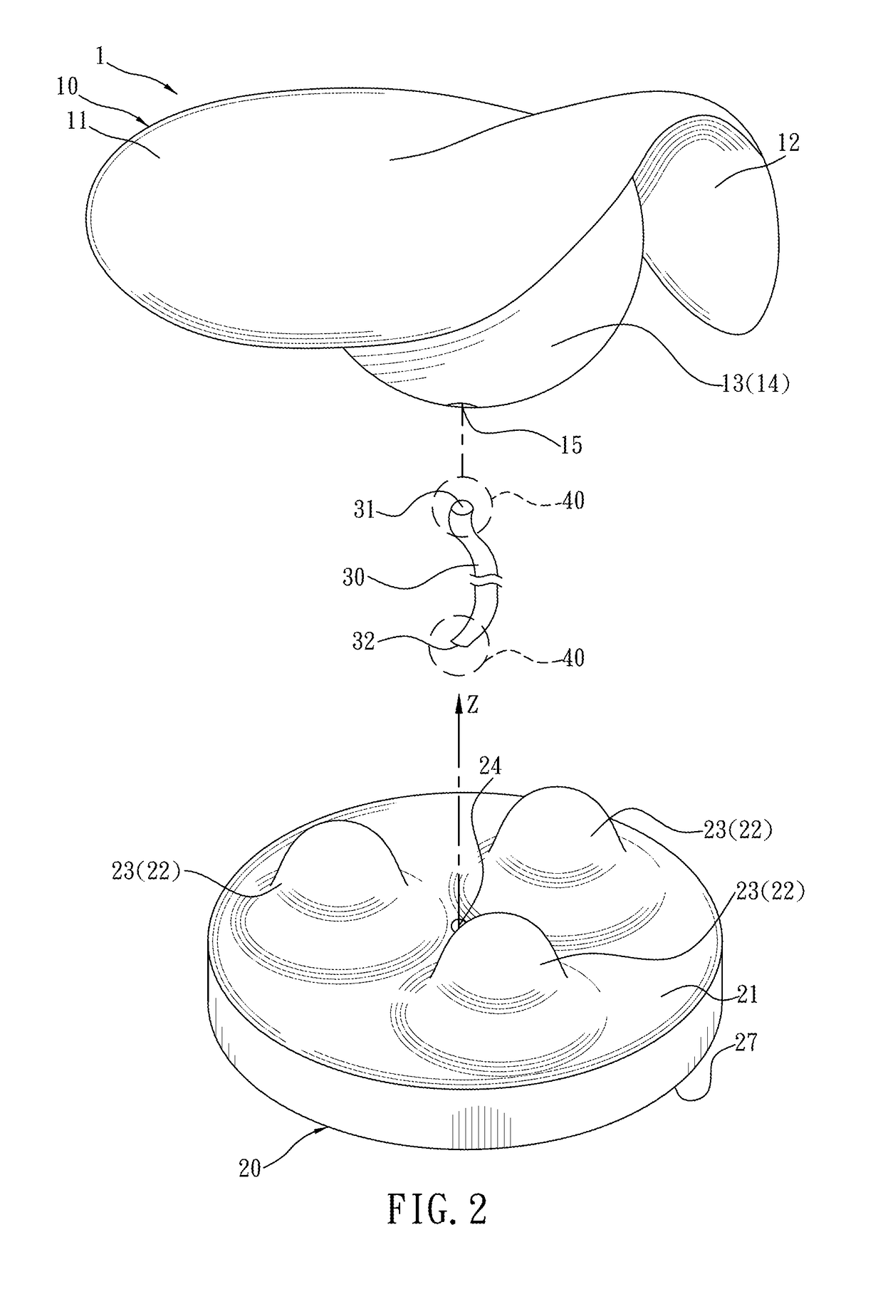
[0017]Refer to FIG. 1, a seat for hip shaking 1 of the present invention includes a seat member 10 and a base member 20. The seat member 10 consists of a saddle-shaped seat surface 11 for users to sit thereon, a bottom surface 12 opposite to the seat surface 11, and a spherical surface 13 projecting downward from the bottom surface 12. A soft member 50 such as pad or leather cover is disposed on the saddle-shaped seat surface 11 of the seat member 10 for users' comfort while they are sitting on the seat member 10, as shown in FIG. 4.

[0018]The base member 20 is arranged under the seat member 10 and at least one support part 22 is set on a top surface 21 thereof. A bottom surface 27 of the base member 20 is, but not limited to, a flat surface that is able to be set stably on a surface of a chair 2, as shown in FIG. 4. Thus the base member 20 will not slide relative to the chair 2 while in use.

[0019]The spherical surface 13 of the seat member 10 is moveably supported by the support par...


PUM


Abstract

A seat for hip shaking is set on a surface of a chair while in use. The seat for hip shaking includes a seat member and a base member arranged under the seat member. A top surface of the seat member is disposed with a saddle-shaped seat surface for users to sit thereon while a spherical surface is projecting downward from a bottom surface of the seat member. The base member has at least one support part on a top surface thereof. The spherical surface of the seat member is moveably supported by the support part of the base member and is rotated at an arbitrary angle. When a user sits on the saddle-shaped seat surface, he/she shakes the hip or maintains the balance to get the benefits of exercise like horse riding.

Description

BACKGROUND OF THE INVENTION[0001]The present invention relates to a seat for hip shaking, especially to a seat by which users can shake their hips or maintain their balance while the seat is set on a surface of a chair.[0002]Body vibration machines such as hip shaking device allowing users to sit thereon for sports and fitness are available on the market now due to greater attention to the health. The user sits on the hip shaking machine, does the wiggle motion by the hip, or maintains his / her posture for fitness. Yet the conventional body vibration machine has certain limitations in the design. For example, the user can't move toward the direction he / she needs smoothly and easily. The vibration direction / angle has been set in advance. The device is less efficient.[0003]Thus there is room for improvement and a need to provide a novel device for solving the problems mentioned above.SUMMARY OF THE INVENTION[0004]Therefore it is a primary object of the present invention to provide a se...

Claims


Application Information

Patent Timeline
IPC IPC(8): A63B21/00A47C9/00A47C7/02A63B23/02A63B26/00
CPCA47C9/002A63B23/02A63B26/003A47C7/021A63B22/18A63B23/0211A63B2208/0233A63B21/4033A47C7/029
Inventor JEN, LI-WEN
Owner TECVIEW GRP CO LTD
Why Eureka
Try Eureka