Friction-based orthotic impedence modulation device
a technology of orthotic impedence and modulation device, which is applied in the field of friction-based orthotic impedence modulation device, can solve the problems of low gait speed, joint pain, and limited orthotic options for this population, and achieve the effect of low stiffness and high stiffness
- Summary
- Abstract
- Description
- Claims
- Application Information
AI Technical Summary
Benefits of technology
Problems solved by technology
Method used
Image
Examples
experimental examples
[0087]The invention is now described with reference to the following Examples. These Examples are provided for the purpose of illustration only and the invention should in no way be construed as being limited to these Examples, but rather should be construed to encompass any and all variations which become evident as a result of the teaching provided herein.
[0088]Without further description, it is believed that one of ordinary skill in the art can, using the preceding description and the following illustrative examples, make and utilize the present invention and practice the claimed methods. The following working examples therefore, specifically point out the preferred embodiments of the present invention, and are not to be construed as limiting in any way the remainder of the disclosure.
example 1
d Compliance Testing of a Stance Control Orthosis
[0089]As shown in FIG. 17, a quasi-passive complaint stance control orthosis (SCO) was constructed that supports the knee in the stance phase of the gait by implementing a spring in parallel with this joint (as an improvement to the current devices that rigidly lock the knee in stance), and allows for free motion in the rest of the gait. It is demonstrated herein how the SCO exhibits multiple levels of stiffness at different phases of the gait through engagement and disengagement of a linear spring in parallel with the knee. The control algorithm decides whether to engage the spring depending on the gait phase, and how the spring stiffness and assistance duration can be adjusted for users with different forms and levels of impairment.
Moment-Angle Performance of Healthy Knee
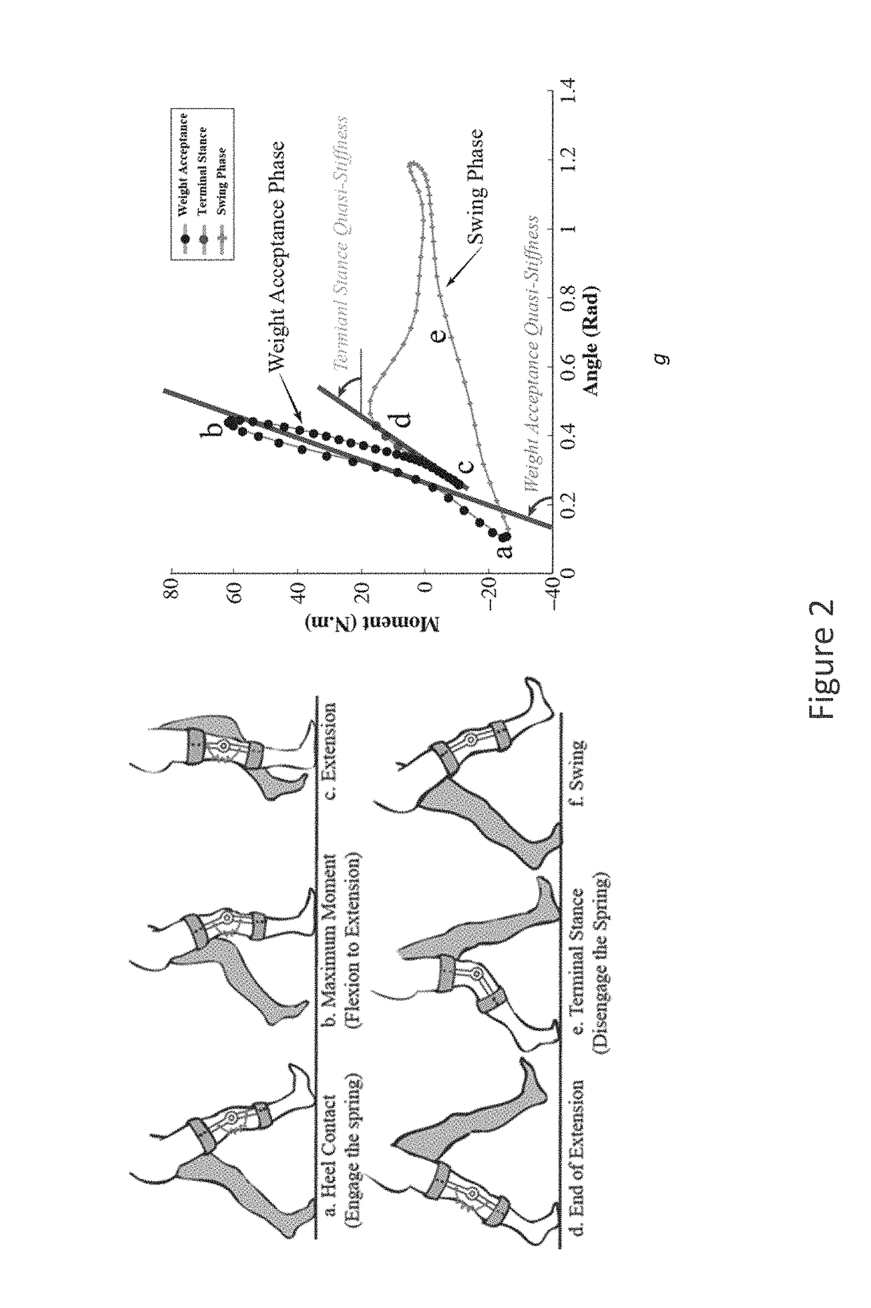
[0090]FIG. 18 shows the schematic posture of the lower extremity limbs during a gait cycle and FIG. 19 shows the moment angle graph of the knee in walking on level ...
example 2
l and Functional Evaluation
[0111]Three additional tests were conducted to evaluate / measure the reliability, latency and endurance of a CSCO, and also the kinematic performance of three healthy volunteers using the CSCO, including a comparison to a commercial SCKAFO (Sensor Walk by Otto Bock).
Preclinical Static Loading
[0112]Applicants measured the moment-angle performance of the device and the maximum moment that the device can hold. Applicants mounted the CSCM on a test bench and applied a series of moments under three levels of stiffness and three angles of engagement. For each condition, Applicants recorded the flexion angle at which the CSCM was stabilized. FIG. 25 shows the results of the experiment wherein the device employed a return spring with linear stiffness of 5 N·mm-1 (equivalent to 13 N·m·rad-1), and support springs with linear stiffnesses of: a. 92 N·mm-1 (equivalent to 239 N·m·rad-1), b. 42 N·mm-1 (equivalent to 127 N·m·rad-1), and c. 34 N·mm-1 (equivalent to 89 N·m·r...
PUM
 Abstract
Description
Claims
Application Information
 - R&D
- Intellectual Property
- Life Sciences
- Materials
- Tech Scout
- Unparalleled Data Quality
- Higher Quality Content
- 60% Fewer Hallucinations
Browse by: Latest US Patents, China's latest patents, Technical Efficacy Thesaurus, Application Domain, Technology Topic, Popular Technical Reports.
© 2025 PatSnap. All rights reserved.Legal|Privacy policy|Modern Slavery Act Transparency Statement|Sitemap|About US| Contact US: help@patsnap.com


