
Thoracic drainage device having reduced counter-pressure

a technology of thoracic drainage and counter-pressure, which is applied in the field of thoracic drainage devices, can solve problems such as cases not beneficial to the healing process, and achieve the effect of facilitating the patient's force to air

Active Publication Date: 2017-12-12
MEDELA HLDG AG
View PDF10 Cites 0 Cited by
  • Summary
  • Abstract
  • Description
  • Claims
  • Application Information

AI Technical Summary

Benefits of technology

The present invention provides a thoracic drainage device that makes it easier for patients to force air out of the pleural cavity. The device has a controllable valve that can change its operating state without manual input, allowing for low counterpressure during air release. The device can also measure the volumetric flow of gas entering the device, which can help in monitoring the healing process. The device is portable, compact, and disposable, with different sizes of secretion collection containers that can be easily coupled to the housing. The control device performs the abovementioned steps and has a digital processor and memory for storing a computer program.

Problems solved by technology

This is in most cases not beneficial to the healing process.

Method used


Image

  • Thoracic drainage device having reduced counter-pressure
  • Thoracic drainage device having reduced counter-pressure
  • Thoracic drainage device having reduced counter-pressure

Examples


Embodiment Construction

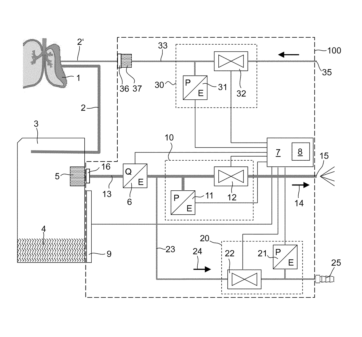
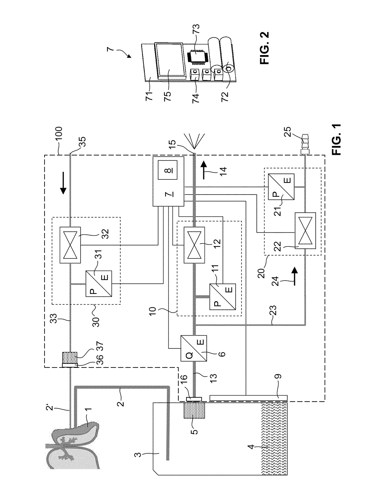
[0058]FIG. 1 is a schematic diagram of a thoracic drainage device 100 according to the invention. The pleural cavity 1 of a patient is connected to a secretion collection container 3 via a drainage catheter (not shown) and via a drainage line 2 attached to said drainage catheter. This secretion collection container 3 is used to separate liquid and gaseous constituents. The liquid secretions 4 collect at the bottom of the secretion collection container 3, while the gaseous constituents (principally air) pass through a filter 5 and via a container connector 16 into a vent line 13. First a flow sensor 6 and then an electrically controllable vent valve 12 are arranged in succession in the vent line 13, as seen in the direction of flow 14. In the opened state, the vent valve 12 frees the vent line 13 to the atmosphere at an outlet 15. A container pressure sensor 11 measures the pressure between the flow sensor 6 and the vent valve 12. This pressure sensor can also be arranged upstream of...


PUM


Abstract

A device for thoracic drainage comprises a container connector for a secretion collection container (3), which can be connected to the pleural cavity of a patient, and a venting device (10) for releasing air from the secretion collection container in passive operation. In order to keep the counterpressure as low as possible during the air release and thus make it easier to force air out of the pleural cavity (1) of a patient, the venting device has a controllable vent valve (12). For this purpose, a control device (7) determines the pressure in the secretion collection container by reading out a pressure sensor (11) and controls the valve to release air from the secretion collection container when the determined pressure exceeds a threshold value. The device can optionally also be operated actively by way of a vacuum connector (25). An ancillary line (2′) permits monitoring of the drainage line (2).

Description

CROSS-REFERENCE TO RELATED APPLICATION[0001]The present application is the United States national phase of International Patent Application No. PCT / CH2012 / 000156, filed Jul. 5, 2012, which application claims priority of Switzerland Application No. 1141 / 11 filed Jul. 7, 2011. The priority application, CH 1141 / 11, is incorporated herein by reference.FIELD OF THE DISCLOSURE[0002]Technical Field[0003]The present invention relates to a device for thoracic drainage and to a corresponding method and computer program.[0004]Prior Art[0005]In patients with defects on the chest wall or lung surface, it is possible for air and secretions to collect in the pleural cavity. This is often treated by carrying out thoracic drainage (pleural drainage), in which air and secretions are removed from the pleural cavity via a drainage catheter. A distinction is made between active systems, in which a vacuum is actively applied to the pleural cavity, and passive systems, which operate without vacuum assista...

Claims


Application Information

Patent Timeline
Patent Type & Authority Patents(United States)
IPC IPC(8): A61M1/00A61B1/015
CPCA61M1/0023A61B1/015A61M2210/101A61M2205/50A61M2205/3331A61M1/732A61M1/743
Inventor EHLERT, HILMAR
Owner MEDELA HLDG AG
Learn More