Temperature responsive thermal bridge

a technology of thermal bridges and thermal bridges, applied in the direction of electromagnetic transmission, modifications by conduction heat transfer, and semiconductor/solid-state device details, etc., can solve the problem of difficult control of heat transfer using conventional thermal bridges

Active Publication Date: 2017-12-12
TYCO ELECTRONICS LOGISTICS AG (CH)
View PDF15 Cites 22 Cited by
  • Summary
  • Abstract
  • Description
  • Claims
  • Application Information

AI Technical Summary

Benefits of technology

[0004]In one embodiment, a thermal bridge between first and second electrical components is provided including a first plate stack, a second plate stack and a temperature responsive actuator. The first plate stack is configured to be placed in thermal communication with the first electrical component. The first plate stack has a plurality of first plates. The second plate stack is configured to be placed in thermal communication with the second electrical component. The second plate stack has a plurality of second plates interleaved with the first plates. The temperature responsive actuator is coupled to at least one of the first and second plate stacks. The temperature responsive actuator changes shape based on changes in temperature to change the relative positions of the first and second plates. The temperature responsive actuator causes the first and second plates to vary thermal resistance between the first and second electrical components based on the change in relative positions of the first and second plates.
[0006]In a further embodiment, an electronic device is provided including a first electrical component, a second electrical component, and a thermal bridge between first and second electrical components. The thermal bridge includes a first plate stack in thermal communication with the first electrical component and a second plate stack in thermal communication with the second electrical component. The first plate stack has a plurality of first plates and the second plate stack has a plurality of second plates interleaved with the first plates. The thermal bridge includes a temperature responsive actuator coupled to at least one of the first and second plate stacks. The temperature responsive actuator changes shape based on changes in temperature to change the relative positions of the first and second plates. The temperature responsive actuator causes the first and second plates to vary thermal resistance between the first and second electrical components based on the change in relative positions of the first and second plates.

Problems solved by technology

However, control of heat transfer is difficult using conventional thermal bridges.

Method used


Image

  • Temperature responsive thermal bridge
  • Temperature responsive thermal bridge
  • Temperature responsive thermal bridge

Examples


Embodiment Construction

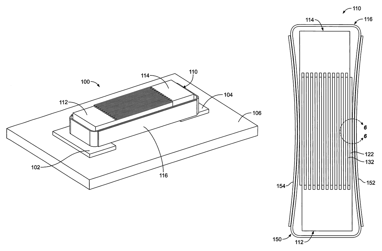
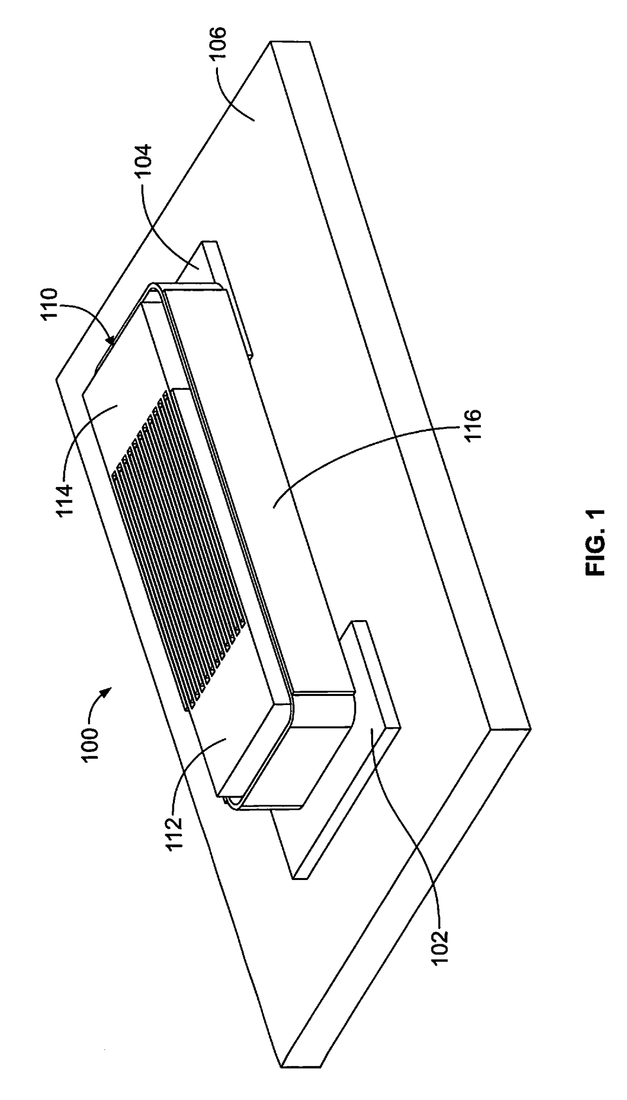
[0013]FIG. 1 illustrates an electronic device 100 formed in accordance with an exemplary embodiment. The electronic device 100 includes a first electrical component 102 and a second electrical component 104 forming parts of electrical systems of the electronic device 100. In the illustrated embodiment, the electronic device 100 includes a circuit board 106 on which the first and second electrical components 102, 104 are mounted. However, in alternative embodiments, the first electrical component 102 and / or the second electrical component 104 may be mounted to another structure or portion of the electronic device 100 rather than being mounted to the circuit board 106. Optionally, the first electrical component 102 and / or the second electrical component 104 may be electrically connected to the circuit board 106, such as to one or more circuits of the circuit board 106. The first and second electrical components 102, 104 may be electrically connected to other electrical components of t...


PUM


Abstract

A thermal bridge includes a first plate stack, a second plate stack and a temperature responsive actuator. The first plate stack is placed in thermal communication with a first electrical component and has a plurality of first plates. The second plate stack is placed in thermal communication with a second electrical component and has a plurality of second plates interleaved with the first plates. The temperature responsive actuator is coupled to at least one of the first and second plate stacks. The temperature responsive actuator changes shape based on changes in temperature to change the relative positions of the first and second plates. The temperature responsive actuator causes the first and second plates to vary thermal resistance between the first and second electrical components based on the change in relative positions of the first and second plates.

Description

BACKGROUND OF THE INVENTION[0001]The subject matter herein relates generally to thermal bridges.[0002]Thermal bridges are used to thermally couple one electrical component with another electrical component of an electronic system to transfer heat to or away from such electrical component. For example, in one particular application, the thermal bridge transfers heat away from one electrical component, such as a processor, to another electrical component, such as a heat sink of the electronic system. In other applications, the thermal bridge is used to heat up an electrical component rather than to remove heat from the electrical component. For example, a heat generating component may be used to heat up a non-heat generating component.[0003]However, control of heat transfer is difficult using conventional thermal bridges. A need remains for a thermal bridge that provides self-regulating heat transfer between electrical components.BRIEF DESCRIPTION OF THE INVENTION[0004]In one embodime...

Claims


Application Information

Patent Timeline
Patent Type & Authority Patents(United States)
IPC IPC(8): H05K7/20G05D23/02H04B10/50
CPCG05D23/02H04B10/503H05K7/20H05K7/2039H01L23/36
Inventor BUCHER, ALAN WEIR
Owner TYCO ELECTRONICS LOGISTICS AG (CH)
Why Eureka
Try Eureka