Camshaft adjuster

a technology of camshaft and adjuster, which is applied in the direction of valve details, engine components, machines/engines, etc., can solve the problems of increased wear, undesirable noise development, and the locking device does not properly lock the rotor, and achieve the effect of implementing the locking action

Active Publication Date: 2018-01-02
SCHAEFFLER TECH AG & CO KG
View PDF22 Cites 4 Cited by
  • Summary
  • Abstract
  • Description
  • Claims
  • Application Information

AI Technical Summary

Benefits of technology

[0008]The present invention provides that the locking pins and the locking gates are situated with respect to each other in such a way that the locking pins lock in the locking gates in reverse order from different directions during a rotation of the rotor from the particular other second “advance” or “retard” stop position in the direction of the central locking position. Due to the proposed approach, the same pair of locking gates and locking pins may be used for locking the rotor from both “advance” and “retard” stop positions. The approach according to the present invention is based on the fact that the locking gates and the locking pins only have to be shaped and situated with respect to each other in such a way that the locking pins lock into the locking gates from different directions during a rotation in both directions, so that the present invention may be implemented without additional costs compared to the prior art.
[0009]It is furthermore proposed that the locking gates are situated and shaped in such a way that the locking gate in which the first locking pin first locks or is locked during a rotation from a first “advance” or “retard” stop position is simultaneously the locking gate in which the last locking pin locks during a rotation of the rotor from the second “advance” or “retard” stop position into the central locking position. As a result, all locking gates used for locking the rotor from one “advance” or “retard” stop position are also used when locking the rotor from the other stop position, so that the number of necessary locking gates may be kept as small as possible with a predetermined number of locking steps.
[0012]It is furthermore proposed that at least three pairs of locking gates and locking pins are provided, and the locking gates are formed by curved, ring segment-shaped recesses or indentations, and the distances between the two locking gates in which the first and the second locking pins lock during a rotation of the rotor from one of the “advance” or “retard” stop positions and the distances between the locking pins locking therein are identical in the circumferential direction. Due to the proposed shaping and arrangement of the locking gates and the locking pins, identical locking paths of the rotor result during the rotary motion from the two stop positions. This also results in the possibility of situating the rotor in two different positions in the stator, if permitted by the pressure medium lines and the vanes of the rotor.
[0013]It is furthermore proposed that the two locking gates in which the first and second locking pins lock during a rotation of the rotor from the “advance” or “retard” stop position are situated axisymmetrically to a middle axis. Due to the axisymmetrical arrangement of the locking gates and the locking pins, the locking action may be implemented from the two stop positions particularly easily and using identical rotation angles.

Problems solved by technology

One problem with camshaft adjusters of this type is that the camshaft adjuster is not yet completely filled with pressure medium in a start phase or may even have been emptied, so that, due to the alternating torques applied by the camshaft, the rotor may execute uncontrolled movements relative to the stator, which may result in increased wear and an undesirable noise development.
In exceptional cases, for example if the internal combustion engine stalls, it is possible, however, that the locking device does not properly lock the rotor, and the camshaft adjuster must be operated with an unlocked rotor in the subsequent start phase.
However, since some internal combustion engines have a very poor start behavior if the rotor is not locked in the central position, the rotor must then be automatically rotated into the central locking position and locked in the start phase.
One disadvantage of the approach described therein is that the automatic locking is always active only during a rotation of the rotor in one direction, i.e., the rotor is automatically locked only during a rotation from an “advance” or “retard” stop position in the direction of the central locking position.
An automatic locking of the rotor from both “advance” and “retard” stop positions in the direction of the central locking position is not possible using the locking devices described therein.

Method used


Image

  • Camshaft adjuster
  • Camshaft adjuster
  • Camshaft adjuster

Examples


Embodiment Construction

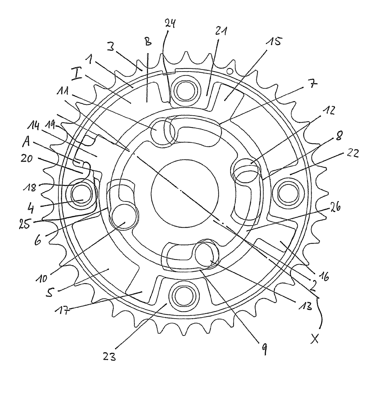
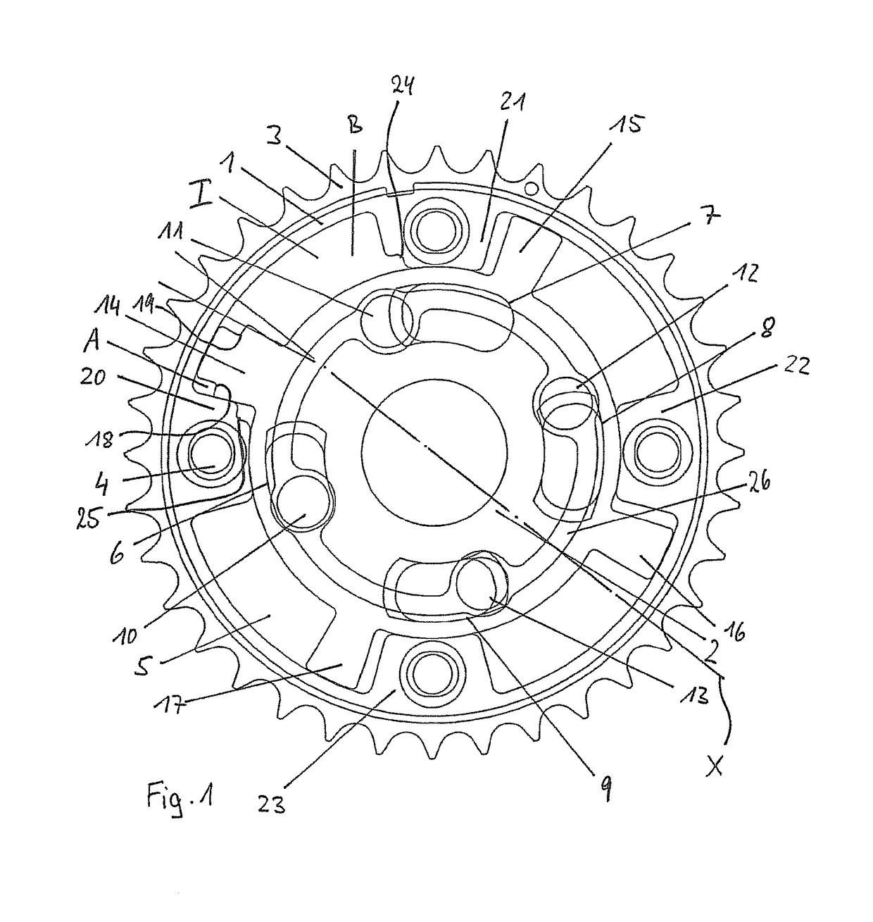
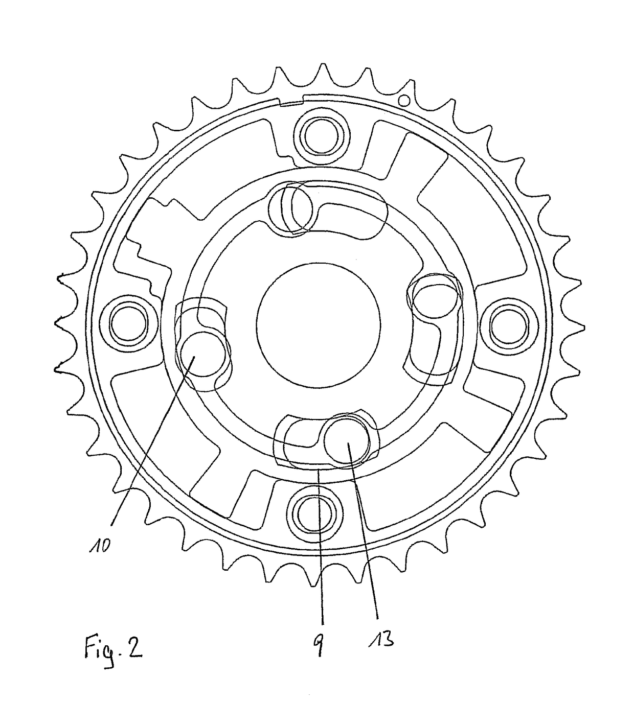
[0023]A camshaft adjuster of an internal combustion engine according to the present invention, including a stator 1 and a rotor 2, is apparent in FIG. 1. Stator 1 has a cup-shaped design and is provided with a toothing 3 on its outside for the purpose of being driven by a crankshaft via a chain or toothed belt. Rotor 2 is connectable to a camshaft in the known manner, e.g., via a central screw, and is driven to a rotary motion with the aid of stator 1. Stator 1 furthermore includes a plurality of stator webs 20, 21, 22, and 23, including threaded bores 4 situated therein, which divide an annular space provided between stator 1 and rotor 2 into multiple pressure chambers I. Rotor 2 includes a plurality of vanes 14, 15, 16 and 17, which extend radially outwardly to the inner wall of stator 1 and divide each pressure chamber I into two working chambers A and B. A translucently represented sealing cover 5 is furthermore provided, which is screwed into threaded bores 4 of stator 1 with t...


PUM


Abstract

A camshaft adjuster has multiple locking guide slots and multiple locking pins spring-loaded in the direction of engagement with the locking guide slots and which, by varying assignment to the rotor and to the stator, are arranged relative to one another such that the rotor can, under the action of fluctuating torques, be automatically locked into the predetermined center position relative to the stator proceeding from a first early or late stop position by a successive engagement of the locking pins into the locking guide slots. The locking pins and the locking guide slots are arranged so that, in the event of a rotation of the rotor in the direction of the center locking position proceeding from the respective other second early or late stop position, the locking pins lock into the locking guide slots in the reverse sequence from different directions.

Description

[0001]The present invention relates to a camshaft adjuster.BACKGROUND[0002]Camshaft adjusters are generally used in valve train assemblies of internal combustion engines to vary the valve opening and closing times, whereby the consumption values of the internal combustion engine and the operating behavior in general may be improved.[0003]One specific embodiment of the camshaft adjuster, which has been proven and tested in practice, includes a vane adjuster having a stator and a rotor, which delimit an annular space, which is divided into multiple working chambers by projections and vanes. A pressure medium may be optionally applied to the working chambers, which is supplied to the working chambers on one side of the vanes of the rotor from a pressure medium reservoir in a pressure medium circuit via a pressure medium pump, and which is fed back into the pressure medium reservoir from the working chambers on the particular other side of the vanes. The control of the pressure medium f...

Claims


Application Information

Patent Timeline
Patent Type & Authority Patents(United States)
IPC IPC(8): F01L1/344
CPCF01L1/3442F01L1/34409F01L2001/34459F01L2250/02F01L2001/34466F01L2001/34469F01L2001/34463
Inventor SCHEIDIG, GERHARDBOESE, OLAFAUM, KIE HEON
Owner SCHAEFFLER TECH AG & CO KG
Why Eureka
Try Eureka