Method and system for detection and compensation of a rapid temperature change on a pressure measurement cell

a technology of pressure measurement cell and temperature change, which is applied in the direction of liquid/fluent solid measurement, instruments, machines/engines, etc., can solve the problems of high insufficient error compensation through the use of two temperature sensors, inability to detect temperature change, and inability to accurately measure the value of the measurement. , to achieve the effect of rapid correction process

Active Publication Date: 2012-01-17
VEGA GRIESHABER GMBH & CO
View PDF11 Cites 4 Cited by
  • Summary
  • Abstract
  • Description
  • Claims
  • Application Information

AI Technical Summary

Benefits of technology

[0013]An aspect of the present invention is to provide a method and system which allows detection of a rapid change in temperature, i.e., a thermal shock without any time lag and with subsequent compensation, while also allowing an implementation without additional costs. This aspect is achieved by a method for detection and compensation of a rapid change in temperature on a pressure measurement cell.
[0021]In another further and optional embodiment, the measured value is corrected on detection of a rapid change in temperature, e.g., a thermal shock, due to the fact that by means of the microprocessor, the integration time for creating the measured the values from the measurement signals is lengthened until the reference values are again within the tolerance band of the expected values of the reference values. This is a very simple and thus also rapid correction process because no additional process steps are necessary in comparison with a convention signal analysis.

Problems solved by technology

A rapid change in temperature, e.g., a so-called thermal shock, may lead to stresses in the diaphragm of the pressure measurement cell, resulting in incorrect measured values due to the resulting deflection of the measurement diaphragm.
What is not appreciated by the prior art is that one disadvantage of this known approach is that with larger measurement ranges (e.g., 60 bar), a change in temperature can be detected only with a time lag because of the thick diaphragm.
However, changes in measurement signal due to thermal shock must take place very rapidly, so that error compensation by means of the two temperature sensors is highly inadequate, in particular when there is a large measurement range.
In addition, the production of such a pressure measurement cell according to EP 1186875 B1 is very complex and, therefore, also expensive, because introducing a temperature sensor into the joint area between the diaphragm and the base body of the pressure measurement cell as well as contacting it and analyzing the signal are associated with additional expense.

Method used


Image

  • Method and system for detection and compensation of a rapid temperature change on a pressure measurement cell
  • Method and system for detection and compensation of a rapid temperature change on a pressure measurement cell
  • Method and system for detection and compensation of a rapid temperature change on a pressure measurement cell

Examples


Embodiment Construction

[0028]Reference will now be made in detail to several embodiments of the invention that are illustrated in the accompanying drawings. Wherever possible, same or similar reference numerals are used in the drawings and the description to refer to the same or like parts or steps. The drawings are in simplified form and are not to precise scale. For purposes of convenience and clarity only, directional terms, such as top, bottom, up, down, over, above, and below may be used with respect to the drawings. These and similar directional terms should not be construed to limit the scope of the invention in any manner. The words “connect,”“couple,” and similar terms with their inflectional morphemes do not necessarily denote direct and immediate connections, but also include connections through mediate elements or devices.

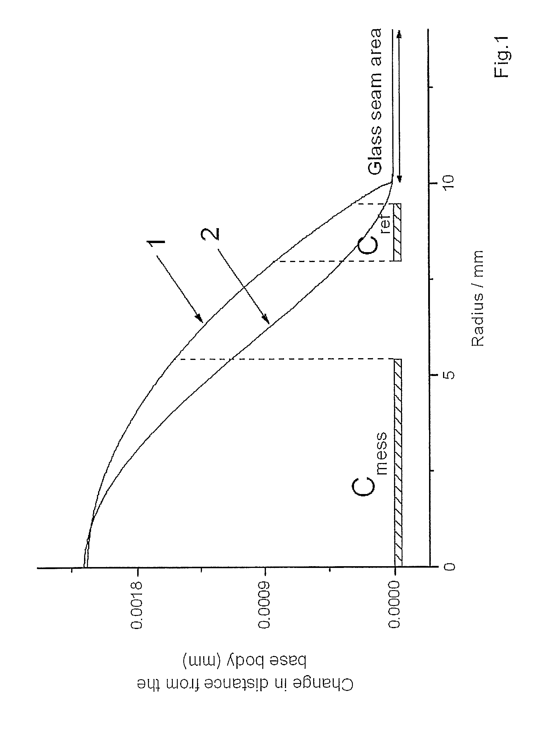
[0029]FIG. 1, illustrates the dependence of the change in distance of the diaphragm from the base body of a pressure measurement cell on the distance from the midpoint of the...


PUM


Abstract

The invention is a method and system for detection and compensation of a rapid change in temperature on a pressure measurement cell, in which a measurement signal proportional to the deflection of a diaphragm is generated by means of a sensor. A reference signal proportional to the deflection of the diaphragm is generated by a second sensor; and, measured values are generated by a microprocessor from the measurement signal while the respective reference values are generated from the reference signal. The reference values are compared with the expected values from a tolerance band, and either a pressure-induced deflection of the diaphragm is detected when there is a correspondence, and the measured values are output as measured values for the measured pressure; or, if there is not a correspondence, a deflection of the diaphragm due to a rapid change in temperature is detected, the measured values are corrected and output.

Description

CROSS REFERENCE TO RELATED APPLICATIONS[0001]This application is related to, and claims priority from, U.S. Provisional Patent Application Ser. No. 61 / 122,299, filed Dec. 12, 2008, and European Patent Application EP 08 020222.9 filed Nov. 20, 2008, the entire contents of each of which are incorporated herein by reference.FIGURE SELECTED FOR PUBLICATION[0002]FIG. 3BACKGROUND OF THE INVENTION[0003]1. Field of the Invention[0004]The present invention relates to a method and system for detection of, and compensation for, the rapid change in temperature on a pressure measurement cell. More specifically, the present invention relates to the detection and measurement of the temperature change by generating a measurement signal and a reference signal proportional to the deflection of a diaphragm and establishing a reference band therefrom.[0005]2. Description of the Related Art[0006]The related art involves the development and use of pressure measurement cells. Pressure measurement cells ar...

Claims


Application Information

Patent Timeline
Patent Type & Authority Patents(United States)
IPC IPC(8): G01F17/00
CPCG01L9/125G01L9/0075
Inventor JACOB, JOERNGRUHLER, HOLGER
Owner VEGA GRIESHABER GMBH & CO
Why Eureka
Try Eureka