
Method of signalling intended to be implemented by a cellular telecommunication network, base station and terminal corresponding thereto

a cellular telecommunication network and signalling technology, applied in the field of telecommunications, can solve the problems of large loss in the sum-rate (total rate) of the network, interference in the capacity of the mobile telecommunication network, and in particular of the lte network, and achieve the effect of improving the sum-rate of the network and improving the performan

Active Publication Date: 2018-02-27
ORANGE SA (FR)
View PDF8 Cites 0 Cited by
  • Summary
  • Abstract
  • Description
  • Claims
  • Application Information

AI Technical Summary

Benefits of technology

[0035]The invention proposes a signaling method in particular for reducing intercellular or MU-MIMO interference evaluated at network level for the purpose specifically of achieving performance that is better in terms of data rate for users, whenever one user is likely to interfere with another, while also improving a sum-rate of the network.
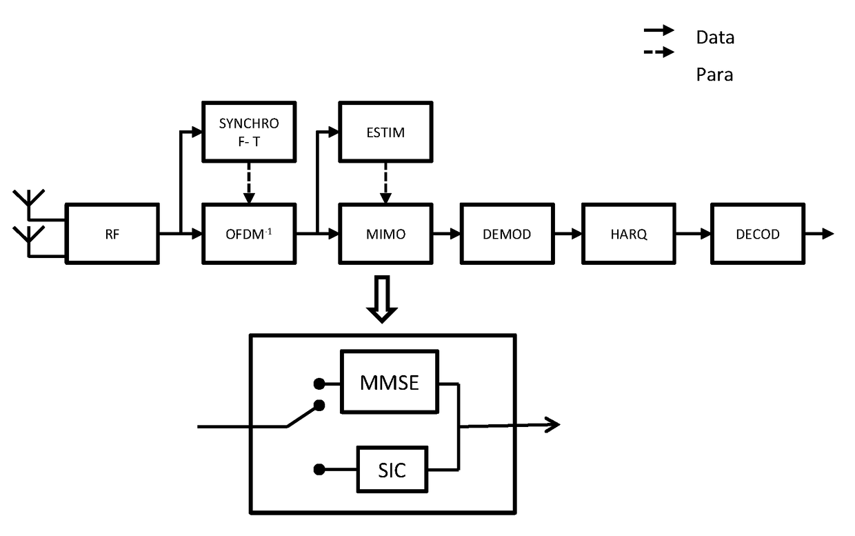
[0048]The indicators selected for returning can make it possible to evaluate the impact on the sum-rate of the network of making use of interference canceling by a receiver. These indicators serve to evaluate the sum-rate in the absence of SIC processing and the sum-rate if SIC processing is activated for the first terminal.
[0051]The signaling method thus makes it possible on all occasions to avoid decreasing the sum-rate, by determining whether or not to activate interference canceling processing as a function of the impact such interference canceling has on the data rate indicators. The signaling method serves to maximize performance in terms of improvement in data rate as seen by the network by taking advantage of the potential for interference canceling by SIC terminals. The data rate to be allocated to the second terminal should be the smaller of the data rate it is capable of receiving and of the data rate corresponding to the indicator returned by the first terminal for the maximum reception rate of the signal to the other terminal. Performance can be maximized by preventing a data rate being allocated to the second terminal that is below a certain threshold, e.g. set as a function of its returned indicator of the maximum reception rate without interference canceling.
[0058]In this implementation, the base station controlling the server transmission point of the first terminal can determine whether interference canceling needs to be activated and can determine the data rates to be allocated. This implementation is particularly suitable when the base station hosts a scheduler that is common to both transmission points.

Problems solved by technology

In known manner, the capacity of a mobile telecommunications network, and in particular of an LTE network, is limited by interference.
The simplicity of that technique is accompanied by sub-optimal use of the radio spectrum, which is not satisfactory given the fact that the terminals are basic receivers, i.e. conventional or advanced linear receivers that do not include interference canceling means; such receivers therefore handle interference as noise and they are referred to below in this document as interference as noise (IaN) receivers.
Maximizing the rate of one link independently of the other links can make interference canceling impossible, which can lead to a major loss in the sum-rate (total rate) of the network, as explained below.
Nevertheless, it remains very difficult to perform link adaptation at network level for the purpose of taking advantage of interference canceling receivers in order to reduce the effect of intercellular interference on the performance of the network.
However such a reduction in allocated data rate can have a negative impact on the sum-rate (SR) of the network.

Method used


Image

  • Method of signalling intended to be implemented by a cellular telecommunication network, base station and terminal corresponding thereto
  • Method of signalling intended to be implemented by a cellular telecommunication network, base station and terminal corresponding thereto
  • Method of signalling intended to be implemented by a cellular telecommunication network, base station and terminal corresponding thereto

Examples


Embodiment Construction

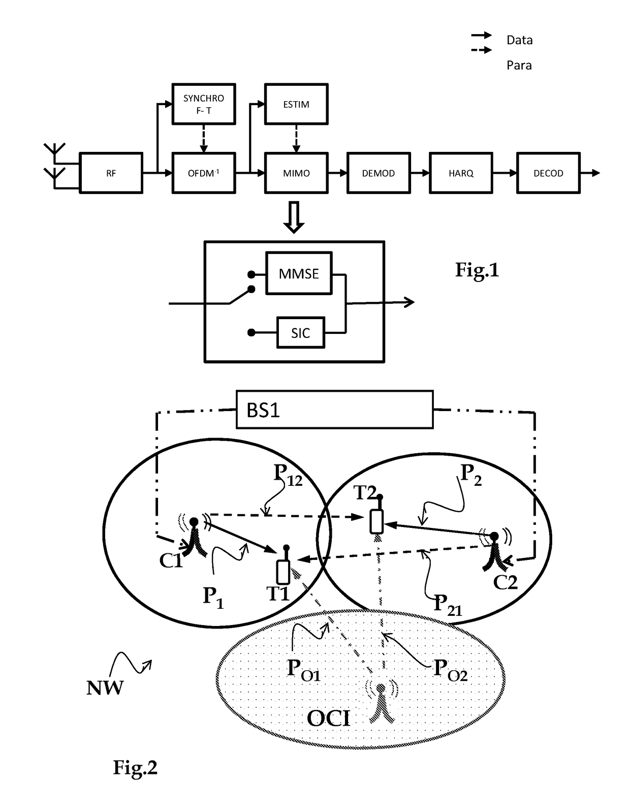
[0090]The invention lies in the context of a network having at least one base station, a terminal, and a transmission point that serves the terminal, which terminal might suffer interference from a signal for a second terminal. The second terminal is served by a second access point generating the interfering signal. The second access point is referred to as the “interferer”.

[0091]The following description refers to FIG. 2, which for reasons of clarity in the drawing, shows two distinct transmission points C1, C2 respectively serving two terminals T1, T2. This figure is not limiting and serves solely for the purposes of illustration.

[0092]A transmission point designates the entity serving a terminal, where the terms “transmission point” and “transmitter” are equivalent. A transmission point corresponds to a cell. In a network complying with the specifications of 3GPP LTE Release 11, a cell may correspond to a plurality of transmission points.

[0093]A terminal is served by its server t...


PUM


Abstract

A method is implemented by a cellular telecommunications network. The method includes: returning indicators from first and second terminals to the network, including, for the respective terminal, an indicator of a maximum reception rate without interference canceling in the presence of an interfering signal, and, for the first terminal, both an indicator of the maximum reception rate with interference canceling in the presence of the interfering signal, and an indicator of the maximum reception rate of the interfering signal; the network determining whether to activate interference canceling by the first terminal and determining respective data rates to be allocated to the first and second terminals as a function of the returned indicators; the network notifying the first terminal whether to activate interference canceling and modifying the first and second terminals of the allocated data rates; the network signaling to the first terminal the data rate allocated to the second terminal.

Description

CROSS-REFERENCE TO RELATED APPLICATIONS[0001]This Application is a Section 371 National Stage Application of International Application No. PCT / FR2014 / 052014, filed Aug. 1, 2014, which is incorporated by reference in its entirety and published as WO 2015 / 022461 A1 on Feb. 19, 2015, not in English.FIELD OF THE INVENTION[0002]The present invention relates to the field of telecommunications. Within this field, the invention relates more particularly to so-called “digital” communications. Digital communications include in particular wireless communications. The communication transmission medium is commonly referred to as a transmission channel or a propagation channel, by analogy with a channel over the air.[0003]The invention relates more particularly to signaling terminal configuration parameters to a terminal in order to enable the terminal to communicate with a cellular telecommunications network.[0004]The invention thus has a preferred, but non-limiting, application in the context o...

Claims


Application Information

Patent Timeline
Patent Type & Authority Patents(United States)
IPC IPC(8): H04J3/14H04J11/00H04L5/00
CPCH04J11/0026H04L5/0035H04J11/0053
Inventor HARDOUIN, ERICJARAMILLO REMIREZ, DANIELKOUNTOURIS, MARIOS
Owner ORANGE SA (FR)
Learn More