Colored electrophoretic displays

a technology of electrophoretic displays and colored dyes, applied in the field of colored electrophoretic displays, can solve the problems of inadequate service life of these displays, unable to meet the needs of customers, and gas-based electrophoretic media are susceptible to the same types of problems, so as to improve the bistability of the display

Active Publication Date: 2018-03-20
E INK CORPORATION
View PDF173 Cites 87 Cited by
  • Summary
  • Abstract
  • Description
  • Claims
  • Application Information

AI Technical Summary

Benefits of technology

[0072]The electrophoretic media of the present invention may contain any of the additives used in prior art electrophoretic media as described for example in the E Ink and MIT patents and applications mentioned above. Thus, for example, the electrophoretic medium of the present invention will typically comprise at least one charge control agent to control the charge on the various particles, and the fluid may have dissolved or dispersed therein a polymer having a number average molecular weight in excess of about 20,000 and being essentially non-absorbing on the particles to improves the bistability of the display, as described in the aforementioned U.S. Pat. No. 7,170,670.

Problems solved by technology

Nevertheless, problems with the long-term image quality of these displays have prevented their widespread usage.
For example, particles that make up electrophoretic displays tend to settle, resulting in inadequate service-life for these displays.
Such gas-based electrophoretic media appear to be susceptible to the same types of problems due to particle settling as liquid-based electrophoretic media, when the media are used in an orientation which permits such settling, for example in a sign where the medium is disposed in a vertical plane.
Indeed, particle settling appears to be a more serious problem in gas-based electrophoretic media than in liquid-based ones, since the lower viscosity of gaseous suspending fluids as compared with liquid ones allows more rapid settling of the electrophoretic particles.
The inherent disadvantage of area sharing is that the colorants are always present, and colors can only be modulated by switching the corresponding pixels of the underlying monochrome display to white or black (switching the corresponding primary colors on or off).
Area sharing is especially problematic when mixing yellow because it is lighter than any other color of equal brightness, and saturated yellow is almost as bright as white.
Such a complex arrangement of electrodes is costly to manufacture, and in the present state of the art it is difficult to provide an adequately transparent plane of pixel electrodes, especially as the white state of the display must be viewed through several layers of electrodes.
Multi-layer displays also suffer from parallax problems as the thickness of the display stack approaches or exceeds the pixel size.
However, there are disadvantages to the use of multiple electrophoretic layers located between a single set of addressing electrodes.
In addition, optical losses in an electrophoretic layer closest to the viewing surface (for example, caused by light scattering or unwanted absorption) may affect the appearance of images formed in underlying electrophoretic layers.
None of these patent applications disclose full color display in the sense in which that term is used below.
Some of the aforementioned displays do provide full color but at the cost of requiring addressing methods that are long and cumbersome.
See also U.S. Patent Application Publication No. 2011 / 0134506 and the aforementioned application Ser. No. 14 / 277,107; the latter describes a full color display using three different types of particles in a colored fluid, but the presence of the colored fluid limits the quality of the white state which can be achieved by the display.
In summary, the current state of the art is that full color displays typically involve compromises such as slow switching speeds (as long as several seconds), high addressing voltages or compromises on color quality.

Method used


Image

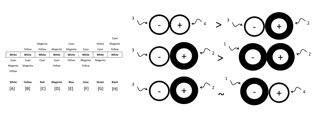
  • Colored electrophoretic displays
  • Colored electrophoretic displays
  • Colored electrophoretic displays

Examples


example 1

Preparation of Yellow Pigment Y1

[0193]A yellow pigment, Novoperm Yellow P-HG (available from Clariant, Basel, Switzerland), (26 g) was combined with Isopar G (70 g) and a solution of Solsperse 19000 (available from Lubrizol Corporation, Wickliffe, Ohio) in Isopar G) and the mixture was dispersed by attriting vigorously with glass beads for 1 hour to afford a yellow pigment dispersion.

example 2

Preparation of Yellow Pigment Y2

[0194]A yellow pigment, Inkjet Yellow 4GC (available from Clariant, Basel, Switzerland), (26 g) was combined with Isopar G (70 g) and a solution of Solsperse 19000 (available from Lubrizol Corporation, Wickliffe, Ohio, 70 g of a 20% w / w solution in Isopar G). The resulting mixture was dispersed by attriting with 250 mL of glass beads for 1 hour at 600 RPM, then filtering through a 200 μm mesh screen to afford a yellow pigment dispersion.

example 3

Preparation of Yellow Pigment Y3

[0195]A yellow pigment, Novoperm Yellow P-M3R (available from Clariant, Basel, Switzerland), (28 g) was combined with Isopar G (70 g) and a solution of Solsperse 19000 (available from Lubrizol Corporation, Wickliffe, Ohio, 70 g of a 20% w / w solution in Isopar G). The resulting mixture was dispersed by attriting with 250 mL of glass beads for 1 hour at 600 RPM, then filtering through a 200 μm mesh screen to afford a yellow pigment dispersion.


PUM

PropertyMeasurementUnit
volume fractionaaaaaaaaaa
thicknessaaaaaaaaaa

Abstract

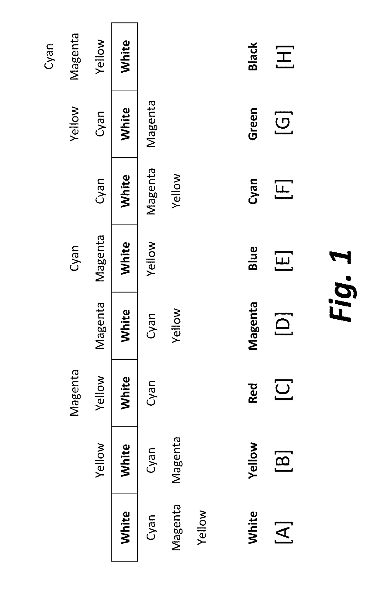
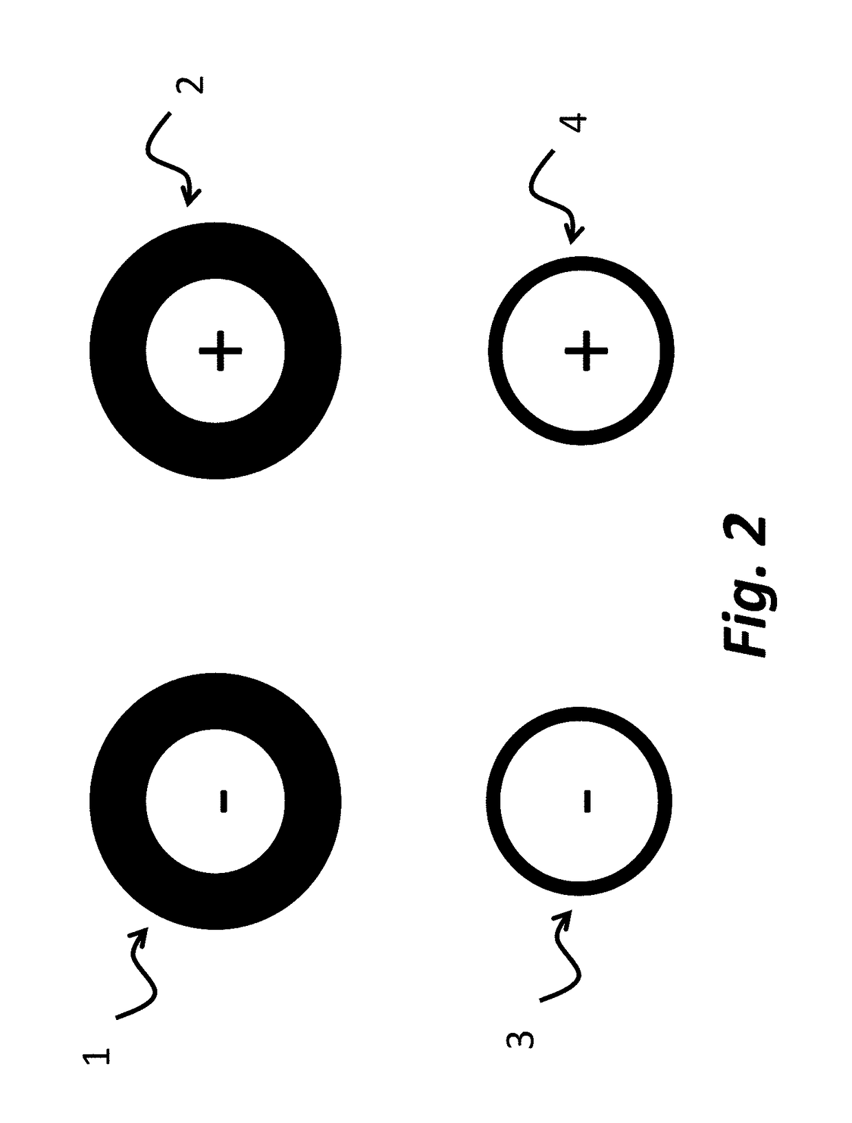
An electrophoretic medium comprises a fluid, a first, light scattering particle (typically white) and second, third and fourth particles having three subtractive primary colors (typically magenta, cyan and yellow); at least two of these colored particles being non-light scattering. The first and second particles bear polymer coatings such that the electric field required to separate an aggregate formed by the third and the fourth particles is greater than that required to separate an aggregate formed from any other two types of particles. Methods for driving the medium to produce white, black, magenta, cyan, yellow, red, green and blue colors are also described.

Description

[0001]This application claims benefit of Application Ser. No. 62 / 048,591, filed Sep. 10, 2014; of Application Ser. No. 62 / 169,221, filed Jun. 1, 2015; and of Application Ser. No. 62 / 169,710, filed Jun. 2, 2015.[0002]This application is related to copending application Ser. No. 14 / 277,107, filed May 14, 2014 (Publication No. 2014 / 0340430), and to application Ser. No. 14 / 279,125, filed Nov. 20, 2014 (Publication No. 2014 / 0340734). The entire contents of these copending applications and of all U.S. patents and published and copending applications mentioned below are herein incorporated by reference.BACKGROUND OF INVENTION[0003]This invention relates to colored electrophoretic displays, and more specifically to electrophoretic displays capable of rendering more than two colors using a single layer of electrophoretic material comprising a plurality of colored particles.[0004]The term color as used herein includes black and white. White particles are often of the light scattering type.[00...

Claims


Application Information

Patent Timeline
Patent Type & Authority Patents(United States)
IPC IPC(8): G02B26/00G02F1/167G02F1/29G02B26/08G09G3/34G02F1/1685
CPCG02F1/167G09G3/344G02F2001/1678G09G3/2003G02F2203/34G02F2201/123G02F2201/121G09G2310/068G09G2310/063G09G2300/0452C09B67/0013G02F1/1685
Inventor TELFER, STEPHEN J.BULL, STEPHENMORRISON, JENNIFER M.SLOMINSKI, LUKE M.MILLER, DAVID DARRELLBARYKINA-TASSA, OLGA VLADIMIROVNAYEZEK, LEEMACDONALD, BRANDONLADAVAC, KOSTAHERB, CRAIG A.
Owner E INK CORPORATION
Why Eureka
Try Eureka