Quadruple sealing structure for can cover

a sealing structure and can cover technology, applied in the field of can covers, can solve the problems of significant manual work, beverage cannot be securely preserved, and the can cover cannot be closed

Active Publication Date: 2018-03-27
LEE SU HO
View PDF14 Cites 2 Cited by
  • Summary
  • Abstract
  • Description
  • Claims
  • Application Information

AI Technical Summary

Benefits of technology

[0014]In an embodiment, the inner circumferential protruding portion and the outer circumferential protruding portion are tightly attached to an inner circumference and an outer circumference of the upper sealing portion to seal an upper surface of the can.
[0019]In an embodiment, wherein a length L1 of the horizontal coupling groove is ⅙ to 1 / 12 of the outer circumference of the inner cover.
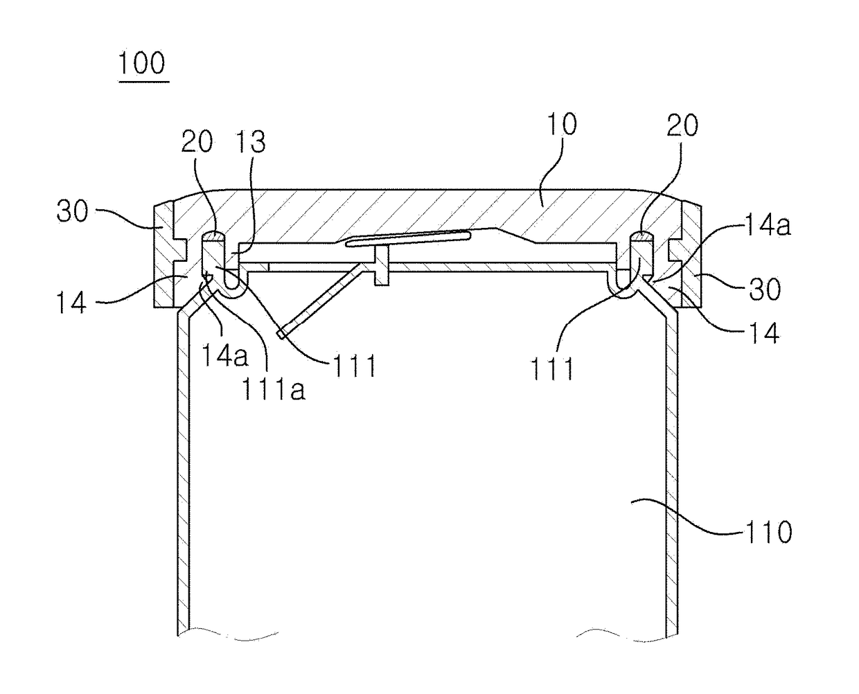
[0038]Yet another object of the embodiments herein is to provide a quadruple sealing structure for a can cover in which the coupling protrusion of an outer coupling ring is inserted into the coupling groove of the inner cover to tighten an outer circumferential protruding portion, thereby making it possible to prevent the upper sealing portion of the can (which is inserted into the circular groove of the inner cover) from being withdrawn from the circular groove and to increase coupling force.
[0038]Yet another object of the embodiments herein is to provide a quadruple sealing structure for a can cover in which the coupling protrusion of an outer coupling ring is inserted into the coupling groove of the inner cover to tighten an outer circumferential protruding portion, thereby making it possible to prevent the upper sealing portion of the can (which is inserted into the circular groove of the inner cover) from being withdrawn from the circular groove and to increase coupling force.

Problems solved by technology

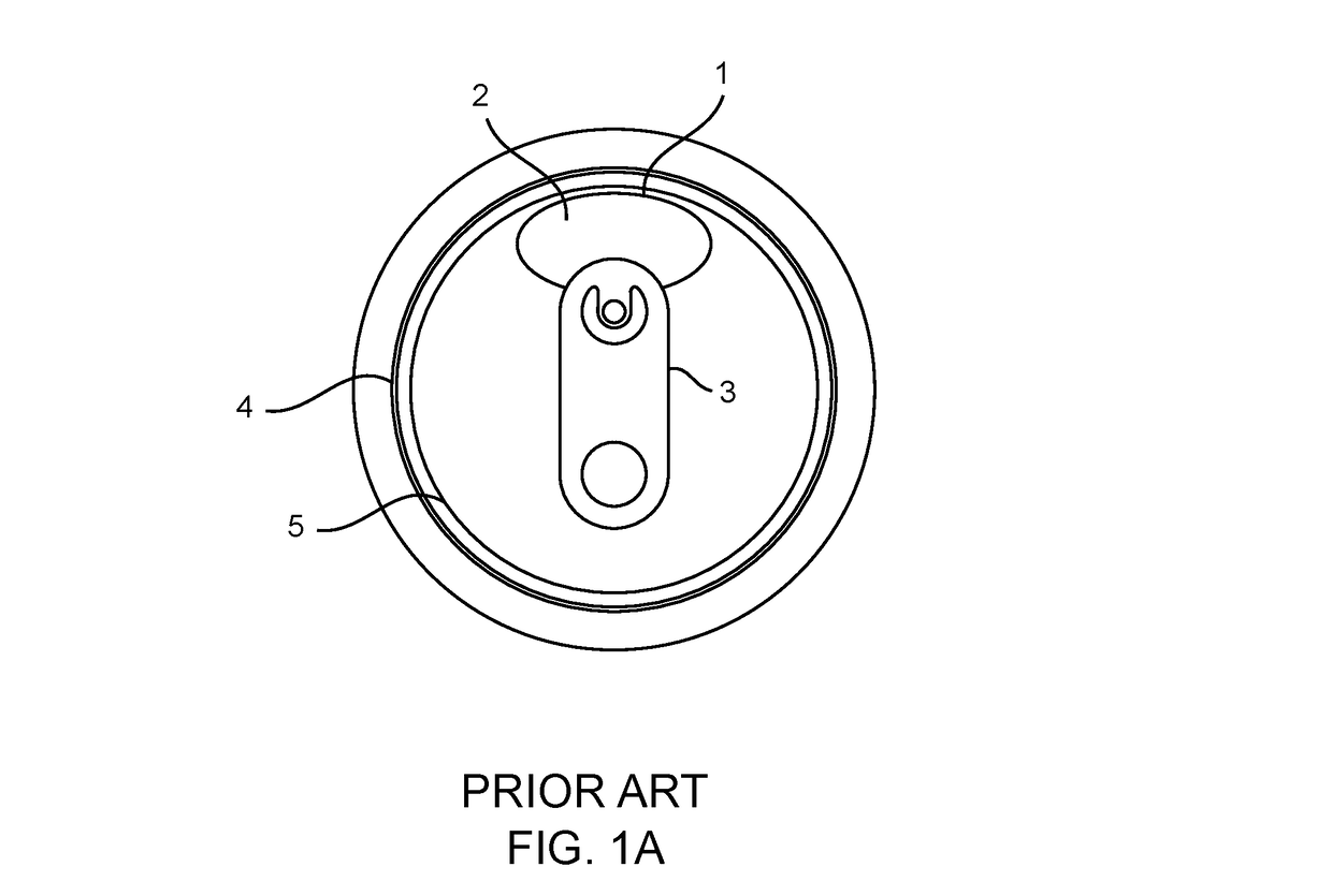
However, once the closure 2 of such beverage can is opened, the opening cannot be closed and the beverage cannot be securely preserved.
However, significant manual work is required for the spiral groove, and as a result, productivity is decreased.

Method used


Image

  • Quadruple sealing structure for can cover
  • Quadruple sealing structure for can cover
  • Quadruple sealing structure for can cover

Examples


Embodiment Construction

[0035]The embodiments herein and the various features and advantageous details thereof are explained more fully with reference to the non-limiting embodiments that are illustrated in the accompanying drawings and detailed in the following description. Descriptions of well-known components and processing techniques are omitted so as to not unnecessarily obscure the embodiments herein. Also, the various embodiments described herein are not necessarily mutually exclusive, as some embodiments can be combined with one or more other embodiments to form new embodiments. The term “or” as used herein, refers to a non-exclusive or, unless otherwise indicated. The examples used herein are intended merely to facilitate an understanding of ways in which the embodiments herein can be practiced and to further enable those skilled in the art to practice the embodiments herein. Accordingly, the examples should not be construed as limiting the scope of the embodiments herein.

[0036]The principal objec...


PUM


Abstract

A can cover having an inner cover comprising a circular groove in which an upper sealing portion of said can is inserted. An inner O-ring is tightly attached to said upper sealing portion of said can. Said inner O-ring is inserted into said circular groove of said inner cover. Also included is an outer coupling ring having a plurality of coupling protrusions inserted into a plurality of coupling grooves formed in an outer circumferential portion of said inner cover. A clearance is formed between said coupling grooves such that when said outer coupling ring is separated from said inner cover, said clearance spreads and separates said inner cover from said upper sealing portion of said can.

Description

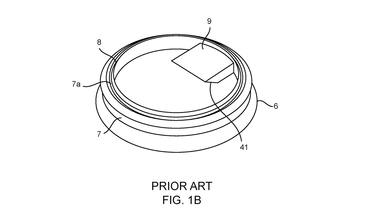
CROSS REFERENCE TO RELATED APPLICATIONS[0001]This application is a continuation-in-part of PCT Application No. PCT / KR2014 / 009085, filed on Sep. 29, 2014, which claims priority to Korea Application No. 10-2014-0002071, filed on Jan. 7, 2014, which are incorporated by reference in their entireties.TECHNICAL FIELD[0002]The present invention relates to a can cover, and more particularly, to a quadruple sealing structure for a can cover, which covers and seals an upper surface of a can to prevent contents stored in the can from leaking outside.BACKGROUND[0003]In general, as shown in a prior art beverage can as illustrated in FIG. 1A, a closure 2 is formed by a scored line 1 which has a deepness smaller than the thickness of an upper portion of a beverage can at one side of the upper surface of the can. A lever 3 is fixed to an upper central portion of the can. In this case, the scored line is not formed near the portion where the lever 3 is installed (that is, a portion near the upper ce...

Claims


Application Information

Patent Timeline
Patent Type & Authority Patents(United States)
IPC IPC(8): B65D53/02B65D51/00B65D17/00
CPCB65D51/007B65D53/02B65D17/4012B65D2517/0098B65D2517/0041B43M11/04B43M11/06B65D25/02B65D43/02B65D83/0011C09J9/005
Inventor LEE, SU-HO
Owner LEE SU HO
Why Eureka
Try Eureka