Electrical Harness

a technology of electrical harnesses and rafts, applied in the direction of insulated conductors, coupling device connections, cables, etc., can solve the problems of compromising the design of aircraft, heavy and difficult to manipulate, and bulky conventional harnesses, and achieve the effect of reducing (or substantially eliminating) the amount, prolonging the life of the electrical harness raft, and reducing the number of anti-vibration mounts that are required to assemble an engin

Active Publication Date: 2018-04-03
ROLLS ROYCE PLC
View PDF190 Cites 5 Cited by
  • Summary
  • Abstract
  • Description
  • Claims
  • Application Information

AI Technical Summary

Benefits of technology

[0018]The electrical conductors embedded in the rigid material may be used to transfer electrical signals around a gas turbine engine. Embedding electrical conductors in a rigid material (to create an electrical harness raft) has a great number of advantages over transferring electrical signals using a conventional harness, at least some of which are discussed herein.
[0058]One or more of the electrical harness rafts may be shaped to correspond to a portion of an outer surface of the fan casing to which they are mounted. In this case, the fan casing may be said to be at least partially surrounded by electrical harness rafts. Conforming the electrical harness rafts to the shape of the fan casing (for example to the shape of the outer surface of the fan casing) may be a particularly compact solution for providing electrical signals around the gas turbine engine, for example around at least a part of the circumference of the gas turbine engine.

Problems solved by technology

This makes the conventional harness bulky, heavy and difficult to manipulate.
The conventional harnesses occupy significant space within a gas turbine engine (for example within the nacelle of a gas turbine engine), and thus may compromise the design of the aircraft, for example the size and / or weight and / or shape of the nacelle.
This can make the assembly process complicated (and thus susceptible to errors) and / or time consuming.
Disassembly of the conventional harnesses (for example removal of the conventional harnesses from a gas turbine engine during maintenance) may also be complicated and / or time consuming.
Thus, in many maintenance (or repair or overhaul) procedures on a gas turbine engine, removal and subsequent refitting of the conventional electrical harness may account for a very significant portion of the operation time and / or account for a significant proportion of the potential assembly errors.
The electrical conductors in the conventional harnesses may be susceptible to mechanical damage.
For example, mechanical damage may occur during installation (for example through accidental piercing of the protective sleeves / braiding) and / or during service (for example due to vibration).
In order to reduce the likelihood of damage to the conductors in a conventional harness, the protective sleeves / braiding may need to be further reinforced, adding still further weight and reducing the ease with which they can be manipulated.

Method used


Image

  • Electrical Harness
  • Electrical Harness
  • Electrical Harness

Examples


Embodiment Construction

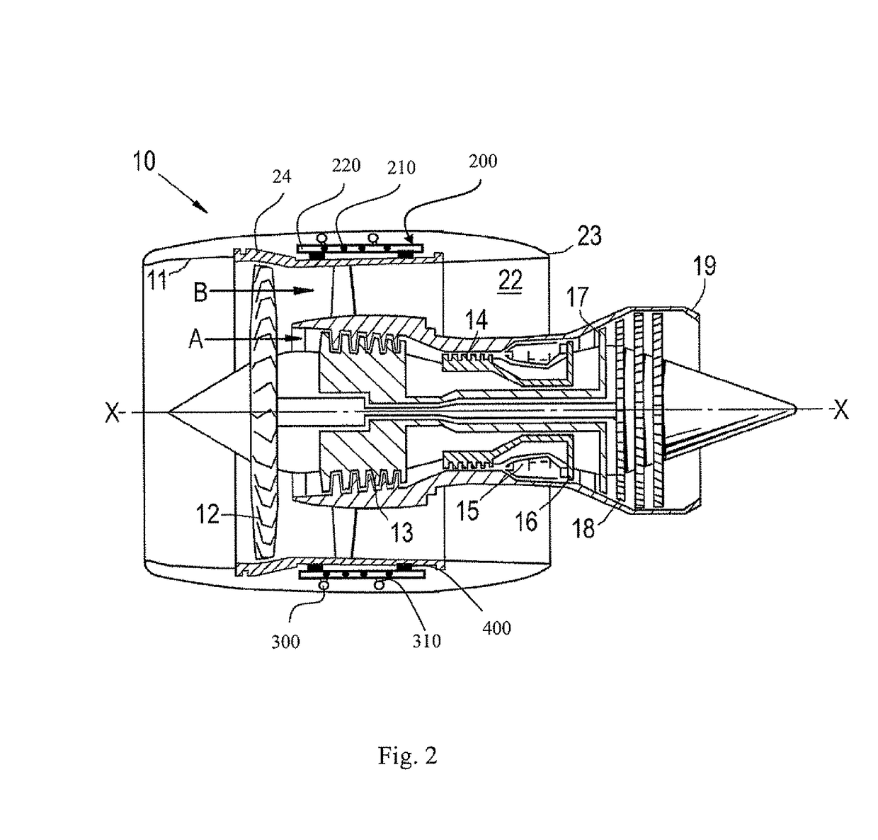
[0077]With reference to FIG. 2, a ducted fan gas turbine engine generally indicated at 10 has a principal and rotational axis X-X. The engine 10 comprises, in axial flow series, an air intake 11, a propulsive fan 12, an intermediate pressure compressor 13, a high-pressure compressor 14, combustion equipment 15, a high-pressure turbine 16, and intermediate pressure turbine 17, a low-pressure turbine 18 and a core engine exhaust nozzle 19. The engine also has a bypass duct 22 and a bypass exhaust nozzle 23.

[0078]The gas turbine engine 10 works in a conventional manner so that air entering the intake 11 is accelerated by the fan 12 to produce two air flows: a first air flow A into the intermediate pressure compressor 13 and a second air flow B which passes through the bypass duct 22 to provide propulsive thrust. The intermediate pressure compressor 13 compresses the air flow A directed into it before delivering that air to the high pressure compressor 14 where further compression takes...


PUM

PropertyMeasurementUnit
electricalaaaaaaaaaa
lengthsaaaaaaaaaa
flexibleaaaaaaaaaa

Abstract

A gas turbine engine 10 is provided with electrical harness rafts 200 comprising electrical conductors embedded in a rigid composite material. The rafts 200 are used to transport electrical signals (which may be, for example power and / or control signals) around a gas turbine engine. Rafts 200 may be connected together and to other components using flexible cables, that may help to accommodate relative movement of the rafts 200, for example through vibration. The rafts 200 are lighter, more compact, and more convenient to handle than conventional electrical harnesses. The rafts 200 may provide a convenient and secure mounting surface for other components / systems of a gas turbine engine, such as EECs and / or fluid pipes.

Description

CROSS-REFERENCE TO RELATED APPLICATIONS[0001]This application is based upon and claims the benefit of priority from British Patent Application Number GB1122140.5 filed 22 Dec. 2011, the entire contents of which are incorporated by reference.BACKGROUND OF THE INVENTION[0002]1. Field of the Invention[0003]This invention relates to a network for distributing signals and power around a gas turbine engine using an electrical harness. In particular, aspects of this invention relate to embedding electrical conductors into a rigid harness for use in distributing electricity around a gas turbine engine.[0004]2. Description of the Related Art[0005]A typical gas turbine engine has a substantial number of electrical components which serve, for example, to sense operating parameters of the engine and / or to control actuators which operate devices in the engine. Such devices may, for example, control fuel flow, variable vanes and air bleed valves. The actuators may themselves be electrically power...

Claims


Application Information

Patent Timeline
Patent Type & Authority Patents(United States)
IPC IPC(8): H01B7/00H05K1/00H05K1/18H01B7/17H01B7/282F02C7/32F02C7/00H01R12/78H01R12/61H05K1/14
CPCH05K1/18H01B7/0045F02C7/00F02C7/32H01B7/17H01B7/282H05K1/00H01R12/61H01R12/78H05K1/144H05K1/147H05K2201/058H05K2201/10295Y02T50/672Y02T50/60F01D25/28H02G3/00Y02A30/14
Inventor BROUGHTON, PAULKENNEA, ROBIN CHARLES
Owner ROLLS ROYCE PLC
Why Eureka
Try Eureka