
Vehicle with transmission having a spline connection

Active Publication Date: 2018-04-26
VOLVO CAR CORP
View PDF3 Cites 2 Cited by
  • Summary
  • Abstract
  • Description
  • Claims
  • Application Information

AI Technical Summary

Benefits of technology

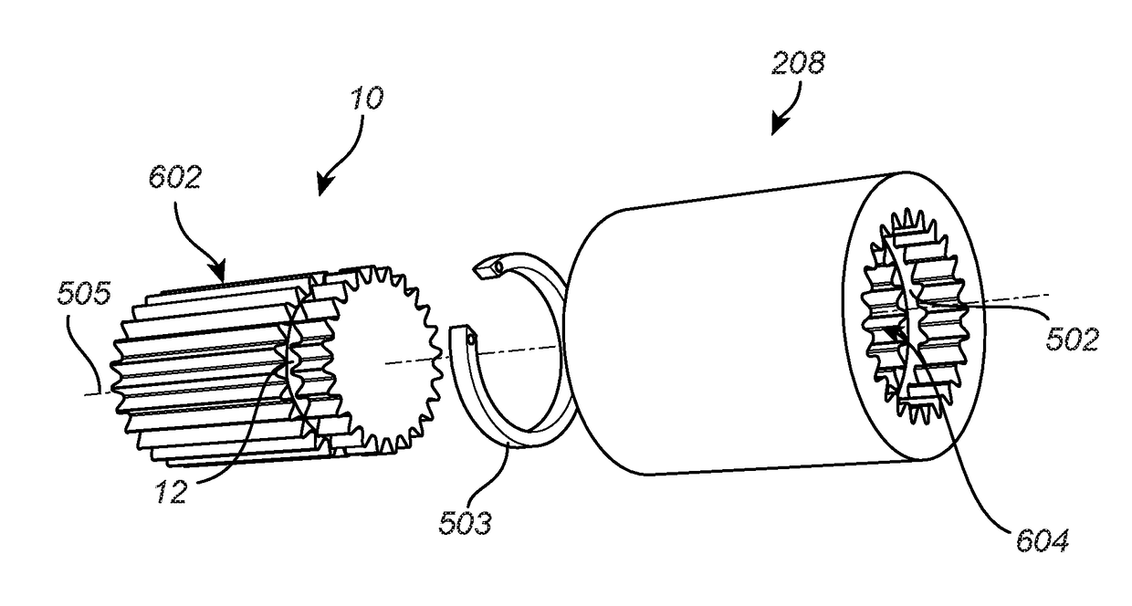
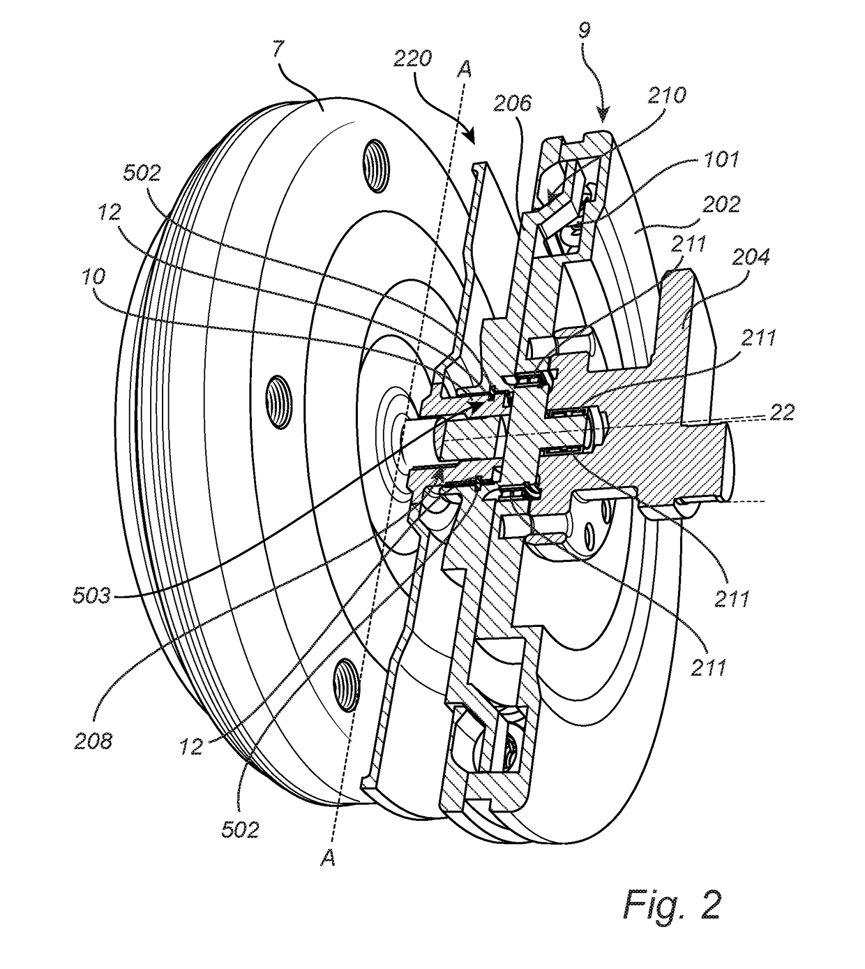
The present invention provides a solution for transmitting controllable torque between an internal combustion engine and a transmission in a compact way. The vehicle has an internal combustion engine, a transmission, and driving wheels. A damping system is used to reduce irregular movements of the engine's crank shaft. The output of the damping system is connected to the transmission, allowing torque from the engine to be transmitted to the wheels. The output of the damping system is designed to match with a splined portion of the transmission's coupling shaft. This allows for a seamless connection between the engine, damping system, and the transmission.

Problems solved by technology

Moreover, a damper system is required for absorbing irregularities in the power output from the ICE which otherwise may be harmful for the transmission of the vehicle or create noise and vibrations.
However, the installation length of the screw joints is relatively large in the cramped space between the torque converter and the ICE.
In powertrain assembly the screw joints for the flexplate may thus lead to tedious and possibly time consuming work.
Torque fluctuations from the ICE will be directly transmitted to the spline connection which may not be a sustainable solution due to for example the durability of the spline connection and may in some cases (e.g. for a diesel ICE) create noise issues.
In addition, the irregularities may be caused by translational sudden axial or radial movement of the crank shaft, or irregularities in the operation of the ICE, for example caused by bending motions of the crank shaft.

Method used


Image

  • Vehicle with transmission having a spline connection
  • Vehicle with transmission having a spline connection
  • Vehicle with transmission having a spline connection

Examples


Embodiment Construction

[0033]In the present detailed description, various embodiments of the system and method according to the present invention are mainly described with reference to a vehicle in the form of a car. However, the present invention mainly equally be used for other types of vehicles such as trucks and busses. Thus, this invention may be embodied in many different forms and should not be construed as limited to the embodiments set forth herein; rather, these embodiments are provided for thoroughness and completeness, and fully convey the scope of the invention to the skilled person. Like reference characters refer to like elements throughout.

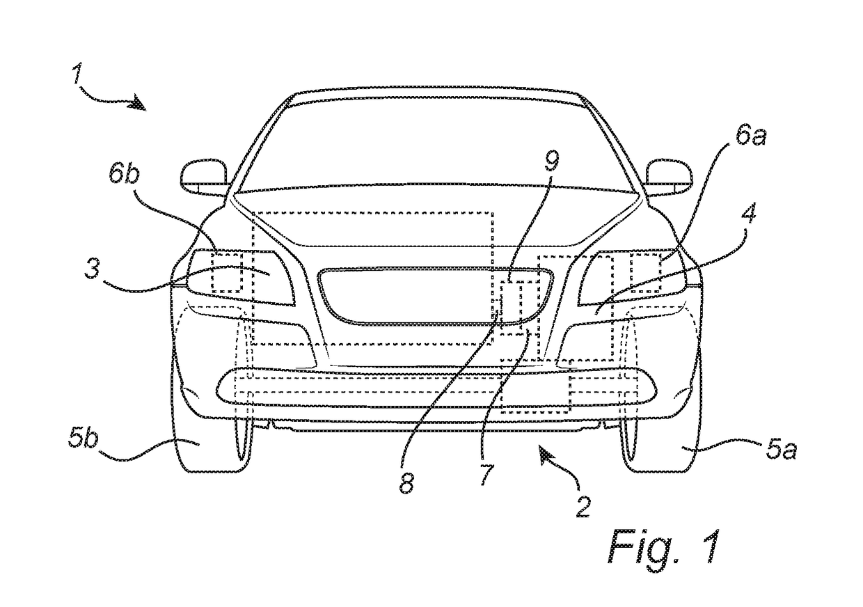
[0034]FIG. 1 schematically shows a hybrid vehicle in the form of a car 1 with a very schematic powertrain 2 indicated with dashed lines to illustrate the limited available transversal space between the side beams 6a, 6b (only conceptually shown) in the body of a modern car. Although not shown, the sub frame of the vehicle also limits the available transv...


PUM


Abstract

The present invention relates to a vehicle comprising: an internal combustion engine operable to rotate a crank shaft of the internal combustion engine; a transmission; at least one driving wheel rotationally connected to the transmission; a damping system arranged between the internal combustion engine and the transmission for dampening irregularity motions of the crank shaft, the damping system comprising an output splined portion; wherein the transmission is arranged for controllably rotationally connecting the output splined portion of the damping system to provide torque from the internal combustion engine to the at least one driving wheel via the transmission, wherein the output splined portion of the damping system is adapted to mate with a splined portion of a coupling shaft of the transmission for connecting the crank shaft to the transmission via the damping system.

Description

RELATED APPLICATION[0001]This application claims priority under 35 U.S.C. § 119 based on European Patent Application No. 16195233.8, filed Oct. 24, 2016, the disclosure of which is hereby incorporated by reference herein.FIELD OF THE INVENTION[0002]The present invention relates to vehicle comprising a damping system and a torque converter connected to a driving wheel via a transmission.BACKGROUND OF THE INVENTION[0003]A vehicle generally comprises a power source such as an electric motor or an internal combustion engine (ICE) with a power output in the form of a rotating crank shaft. For automatic transmission vehicles, the rotating crank shaft is coupled to a torque converter and to a transmission in order to convert the rotating power output to torque for drive wheels. Conventionally, the crank shaft from the ICE is connected to the torque converter via a flexplate. Furthermore, the torque converter in an automatic transmission vehicle generally includes a lock-up clutch to elimin...

Claims


Application Information

Patent Timeline
IPC IPC(8): F16D1/10F16H47/00
CPCF16D1/10F16H47/00F16D2001/103F16H2045/0221B60K17/04B60K17/08F16D1/04F16H57/02F16H2057/02043F16H2057/02026F16F15/1207F16H57/0006F16D1/116F16H2045/0252F16D1/06
Inventor JORGENSSON, MATHIASFORSSELL, JONASHOLMSTROM, JAN CHRISTIANMALM, PER-ARNEDZAFIC, AHMET
Owner VOLVO CAR CORP
Learn More