Slide valve, percussion device & method

a technology of percussion device and slide valve, which is applied in the field of slide valve, can solve problems such as efficiency reduction, and achieve the effect of compact solution and better holding for

Active Publication Date: 2015-03-26
CONSTR TOOLS PC AB
View PDF21 Cites 2 Cited by
  • Summary
  • Abstract
  • Description
  • Claims
  • Application Information

AI Technical Summary

Benefits of technology

[0009]Such a slide valve provides a better holding force since one pin or a plurality of pins holds the slide valve stably in place when the slide valve is mounted in a percussion device and the percussion device is in use. The slide valve has, for example, flat surfaces at each end, which axially seal against corresponding surfaces in the machine housing. Since the pins are at least partly arranged in the slide valve itself, and not in the machine housing, as in U.S. Pat. No. 4,142,447, a more compact solution is achieved.

Problems solved by technology

Usually the seal between the pressure channel and the tank channel consists of only a radial column seal where there will always be some play, and which can give rise to leakage and decreased efficiency.

Method used


Image

  • Slide valve, percussion device & method
  • Slide valve, percussion device & method
  • Slide valve, percussion device & method

Examples


Embodiment Construction

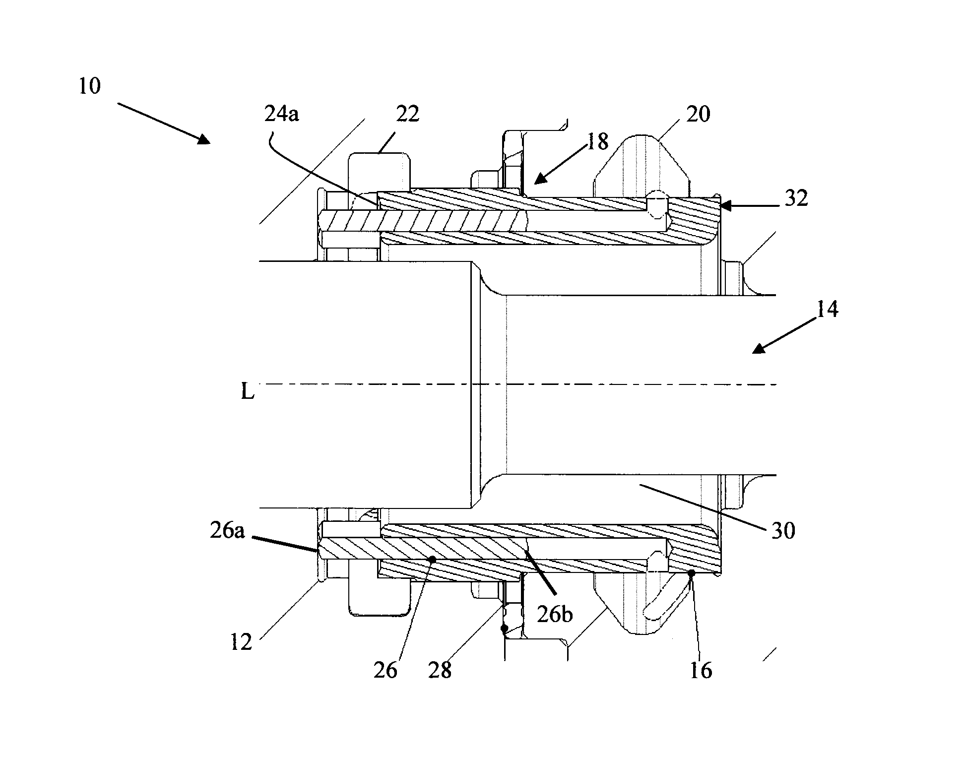
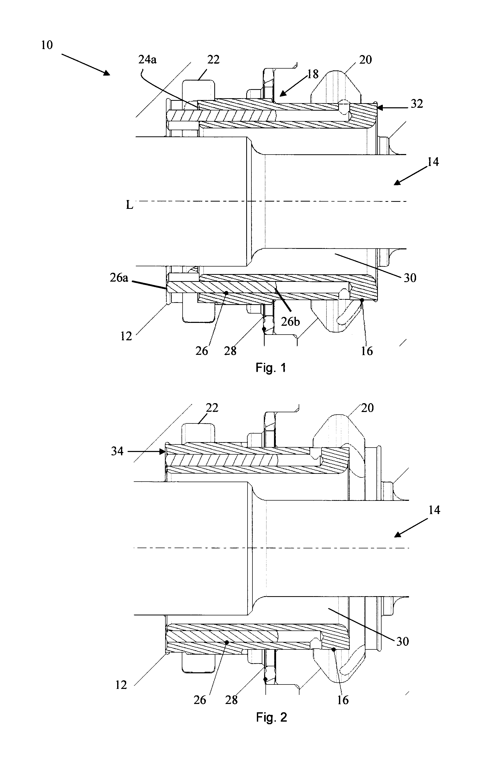
[0029]FIG. 1 shows part of a hydraulic fluid-driven percussion device 10 according to an embodiment of the present invention. The percussion device 10 comprises a machine housing 12 that contains a percussion piston 14. The percussion piston 14 is arranged to carry out a reciprocating movement, for example at a frequency of 10 Hz or higher, along its longitudinal axis L when the percussion device 10 is in use.

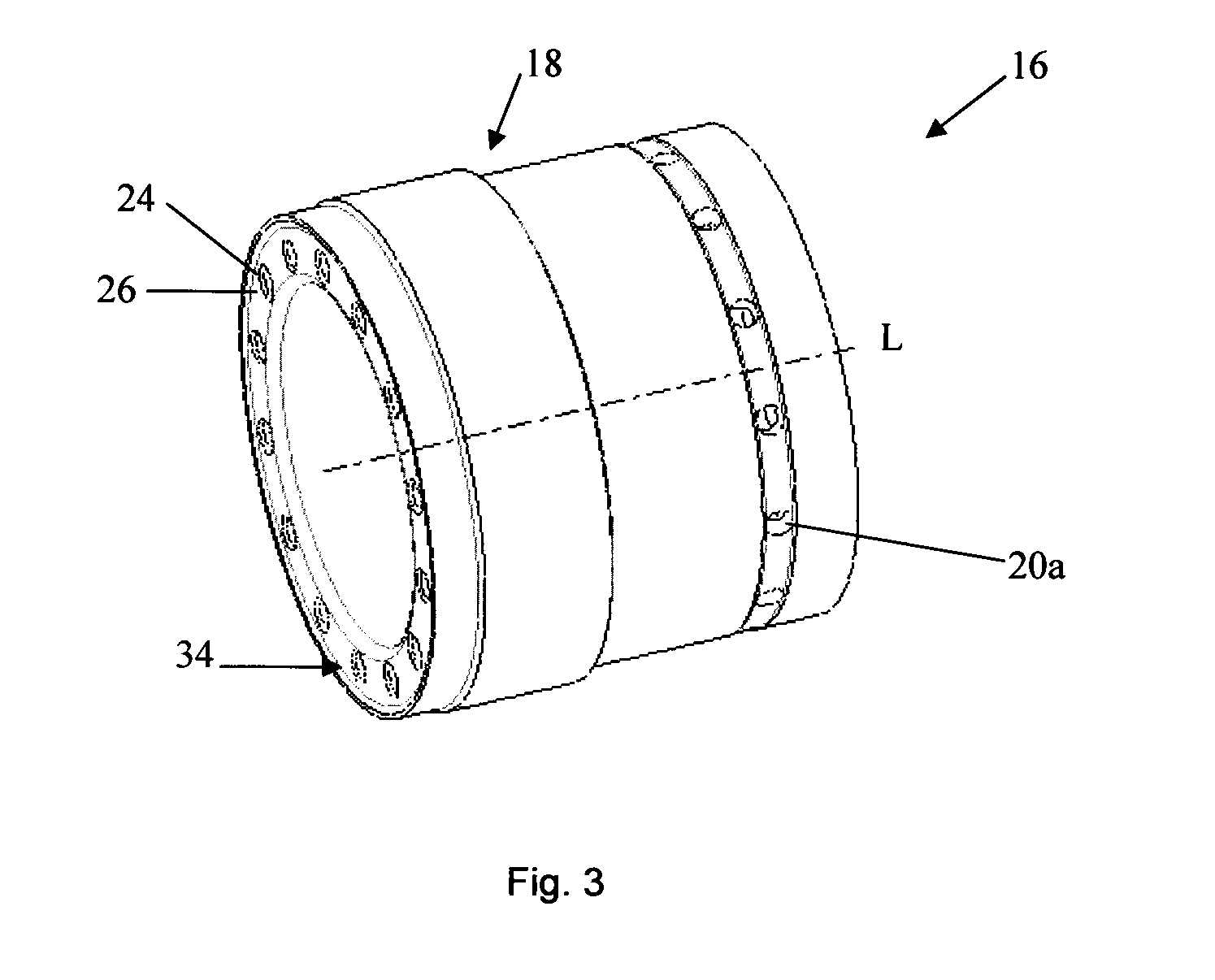
[0030]The percussion device 10 comprises a cylindrical slide valve 16 that comprises a transition surface 18 that is arranged to be alternately subjected to the percussion device's working pressure 20 and tank pressure 22 via a signal channel 28. The slide valve 16 comprises a plurality of channels 24 uniformly distributed around the slide valve's 16 periphery, which channels 24 extend along about 80% of the slide valve's 16 length. The channels 24 can for example be 20-50 mm long, preferably 25-40 mm long. The channels 24 are open at one end 24a of the slide valve 16 and exten...


PUM


Abstract

A slide valve for a hydraulic percussion device. The slide valve includes a transition surface that is arranged to alternately be subjected to a working pressure and a tank pressure to carry out a reciprocating movement when the percussion device is in use. The slide valve includes at least one channel that is open at one end of the slide valve, and at least one displaceable pin that is arranged inside the at least one channel.

Description

TECHNICAL FIELD[0001]The present invention concerns a slide valve for a hydraulic percussion device, and a hydraulic percussion device that contains such a slide valve. The present invention also concerns a method for making a slide valve of a percussion device carry out a reciprocating movement when the percussion device is in useBACKGROUND OF THE INVENTION[0002]Percussion devices often comprise a linearly working percussion piston that is controlled by a slide valve. Usually the slide valve is controlled by a signal channel whose pressure varies. Either a tank pressure or full working pressure acts upon the transition surface of the slide valve via the signal channel.[0003]Usually the seal between the pressure channel and the tank channel consists of only a radial column seal where there will always be some play, and which can give rise to leakage and decreased efficiency. The slide valve can also drift during the percussion piston's displacement and provide an even shorter colum...

Claims


Application Information

Patent Timeline
Patent Type & Authority Applications(United States)
IPC IPC(8): E21B1/02E21B7/02
CPCE21B7/025E21B1/02B25D9/20B25D9/08B25D2250/351
Inventor LUNDGREN, ANDERS
Owner CONSTR TOOLS PC AB
Why Eureka
Try Eureka