High density electrical connector with variable insertion and retention force

Active Publication Date: 2011-09-01
AMPHENOL CORP
View PDF5 Cites 89 Cited by
  • Summary
  • Abstract
  • Description
  • Claims
  • Application Information

AI Technical Summary

Benefits of technology

[0011]An improved connector may be provided by providing relatively low insertion to force and high retention force. The force profile may be achieved with a projection from a connector housing that intercepts a beam during connector mating. Initially during the mating sequence, the beam deflects over i

Problems solved by technology

For example, the mating contact portions of the conductive elements may be positioned along the

Method used


Image

  • High density electrical connector with variable insertion and retention force
  • High density electrical connector with variable insertion and retention force
  • High density electrical connector with variable insertion and retention force

Examples


Example

[0054]This invention is not limited in its application to the details of construction and the arrangement of components set forth in the following description or illustrated in the drawings. The invention is capable of other embodiments and of being practiced or of being carried out in various ways. Also, the phraseology and terminology used herein is for the purpose of description and should not be regarded as limiting. The use of “including,”“comprising,”“having,”“containing,” or “involving,” and variations thereof herein, is meant to encompass the items listed thereafter and equivalents thereof as well as additional items.

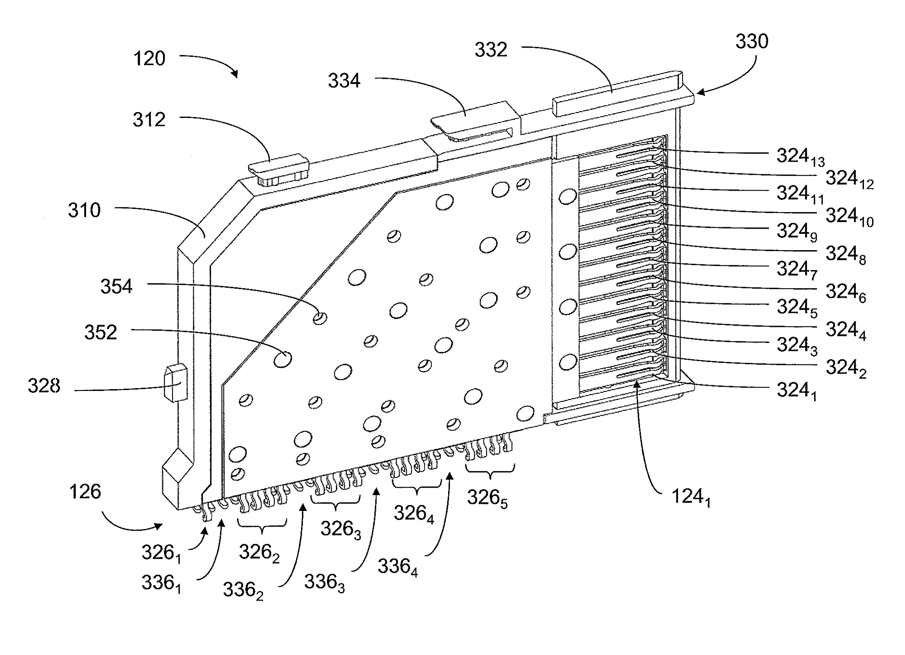
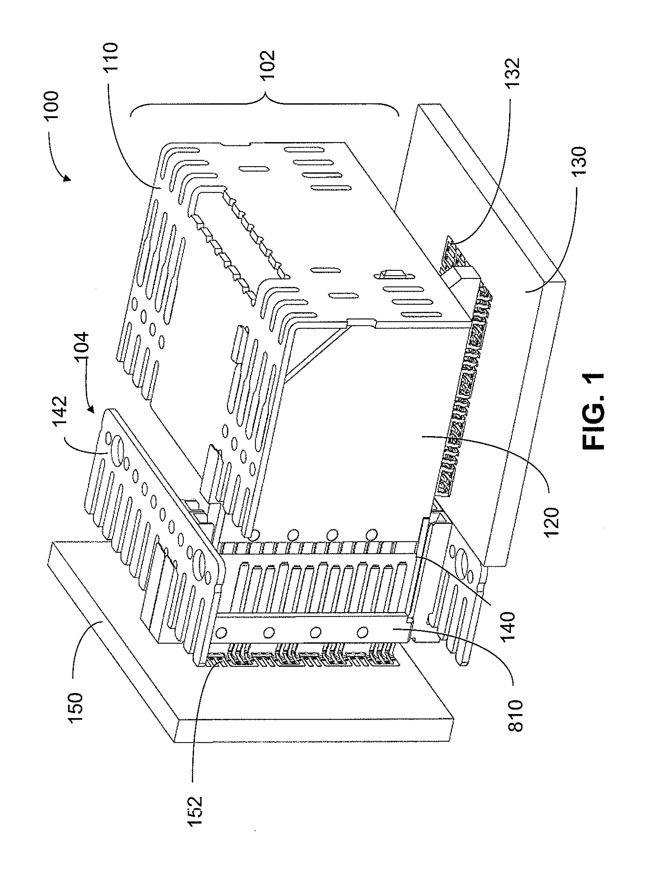
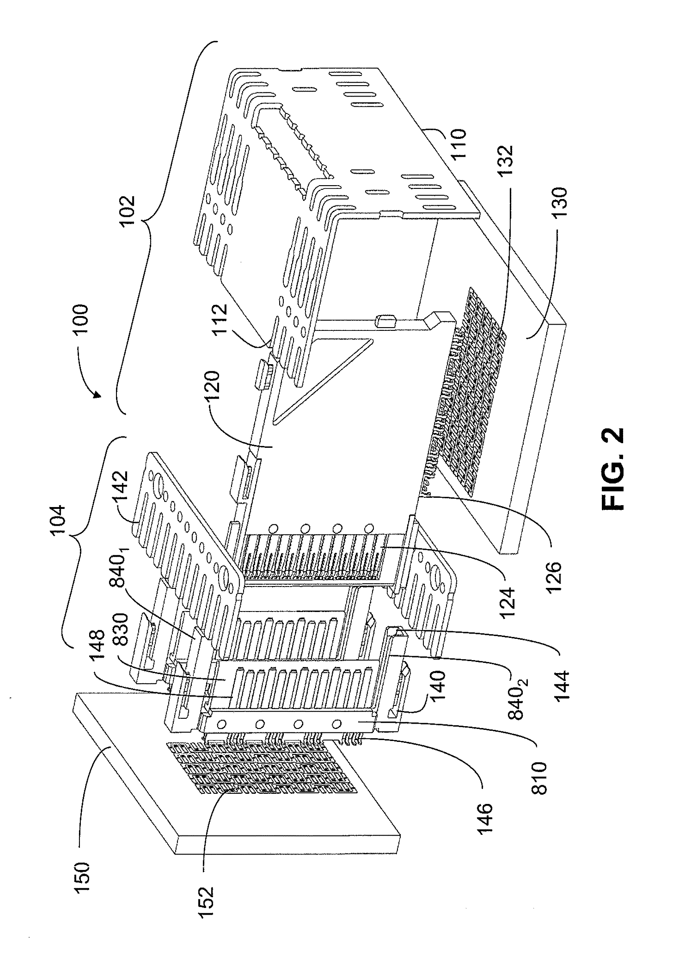
[0055]Referring to FIGS. 1 and 2, an illustrative portion of electrical interconnection system 100 is shown. The electrical interconnection system 100 includes a daughter card daughter card connector 102 and a backplane connector 104, each of which is attached to a substrate to be connected through interconnection system 100. In this example, daughter card daugh...


PUM


Abstract

An interconnection system that includes a daughter card and backplane electrical connectors mounted to printed circuit boards at connector footprints. The spring rate of beam-shaped contacts in the daughter card connector increases while mating with the backplane connector so that the retention force may be greater than the insertion force. Such a change in spring rate may be achieved by positioning the beam-shaped contacts adjacent a surface of a connector housing. That surface may include a projection that aligns with the beam-shaped contact. When the connectors are unmated, the beam-shaped contact may be spaced from the projection. As the connectors begin to mate, a central portion of the beam-shaped contact may be pressed against the projection, which has the effect of shortening the beam length and increasing its stiffness.

Description

RELATED APPLICATIONS[0001]This application is a continuation of PCT Application PCT / US2009 / 005275, filed Sep. 23, 2009 which claims priority to U.S. Provisional Application 61 / 099,369, filed Sep. 23, 2008 which are incorporated herein in their entireties.BACKGROUND[0002]This invention relates generally to electrical interconnections for connecting printed circuit boards.[0003]Electrical connectors are used in many electronic systems. It is generally easier and more cost effective to manufacture a system on several printed circuit boards (“PCBs”) that are connected to one another by electrical connectors than to manufacture a system as a single assembly. A traditional arrangement for interconnecting several PCBs is to have one PCB serve as a backplane. Other PCBs, which are called daughter boards or daughter cards, are then connected through the backplane by electrical connectors.[0004]Electronic systems have generally become smaller, faster and functionally more complex. These chang...

Claims


Application Information

Patent Timeline
IPC IPC(8): H01R24/00H01R12/71
CPCH01R12/721H01R23/688H01R13/6587
Inventor STOKOE, PHILIP T.GAILUS, MARK W.REN, HUILINGIRARD, JR., DONALD A.
Owner AMPHENOL CORP
Why Eureka
Try Eureka