Method and device for the automated handling of resin-impregnated mats during the production of smc parts

Inactive Publication Date: 2005-02-24
DAIMLER AG
View PDF8 Cites 23 Cited by
  • Summary
  • Abstract
  • Description
  • Claims
  • Application Information

AI Technical Summary

Benefits of technology

[0021] The item which is to be handled is in principle secured over the entire top-side surface in the level state and retains this level form while being picked up, transported and while being deposited, irrespective of how soft the resin-impregnated mats are. The suction bells have a cup-shaped cross section with an edge which tapers to a point and can sink into the surface of the mat in a sealing manner. Owing to the grid arrangement of the large number of individually activatable suction bells, the suction gripper can be adapted to different sizes and/or shapes of mat blanks by simple control measures. Owing to the inflexible cup shape, not only is a higher retaining force achieved in comparison with a flexible rubber suction cup of the same size, but also a higher vacuum can be applied without deforming the suction bell. Because the annular cutting edge of the bells sinks into the surface of the mat, provides a very good seal, and likewise makes possible a high vacuum and a high retaining force. In spite of a surface which is rippled and/or provided with superficial pores, additional air do

Problems solved by technology

One disadvantage of the method according to Brüssel et al. is that all of the blanks are rectangular and, in principle, are identical in size, but this can only be readily allowed for a restricted range of components.
A further disadvantage of the arrangement according to Brüssel et al. or the transfer rake according to DE '380 resides in the handling device itself which does not allow a direct weighing of the blanks.
In addition—apart from simple stacking—other processes for handling individual mat blanks using the known handling rake would only be possible if the individual blank rests on an interrupted base shaped specifically for the rake, which is not generally the case.
The positioning accuracy when handling individual mat blanks or an entire stack of resin-impregnated mats suffers, however, because the item to be handled executes an uncontrolled self-movement during the transfer due to the force of gravity and friction.
Since the supporting prongs of the transfer rake define a level depositing surface, but the impression of the lower mold is uneven, the transfer rake has to maintain a certain minimum distance in the vertical direction from the impression during the transfer of the resin-impregnated mats.
Secondly, because of friction, a soft and/or more sticky resin-impregnated mat will stick more strongly onto the supporting prongs of the transfer rake in the withdrawal direction than a stiff and/or less sticky resin-impregnated mat.
It is virtually impossible to detect these influences and compensate for them b

Method used


Image

  • Method and device for the automated handling of resin-impregnated mats during the production of smc parts
  • Method and device for the automated handling of resin-impregnated mats during the production of smc parts
  • Method and device for the automated handling of resin-impregnated mats during the production of smc parts

Examples


Example

DETAILED DESCRIPTION OF THE DRAWINGS

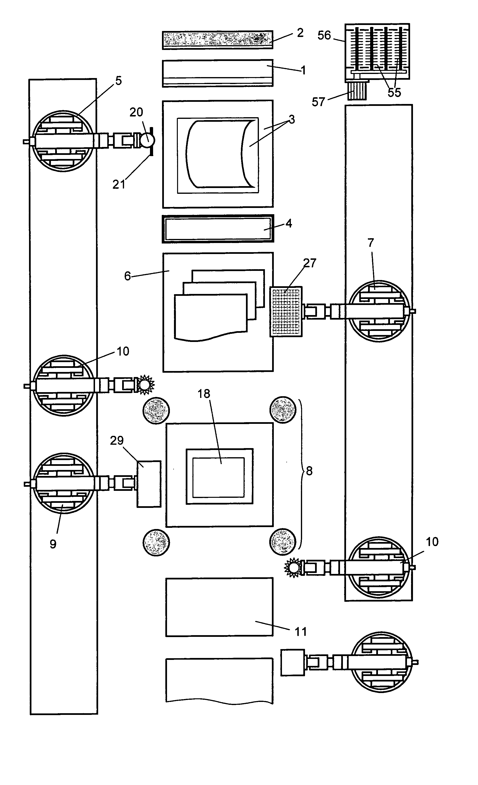
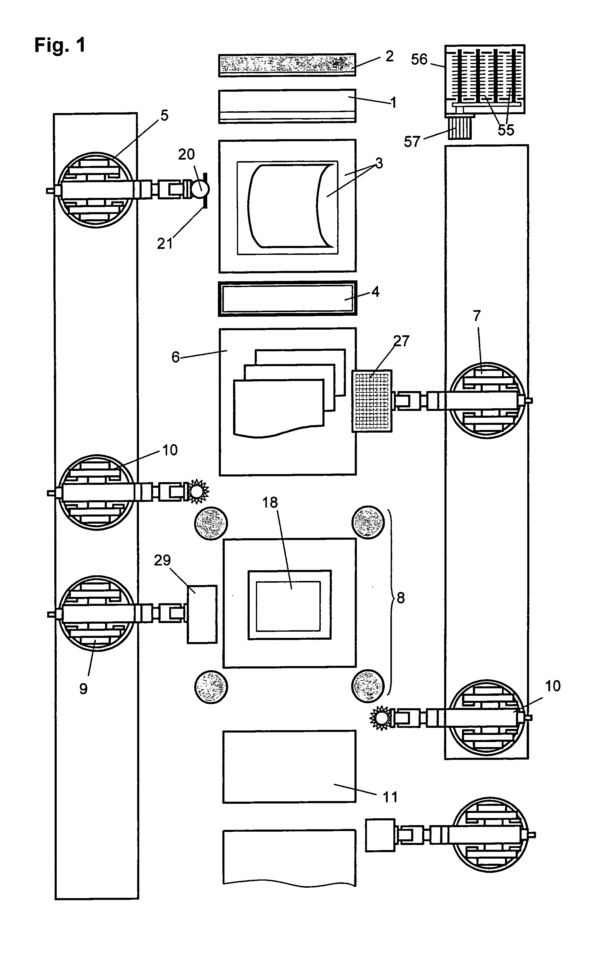
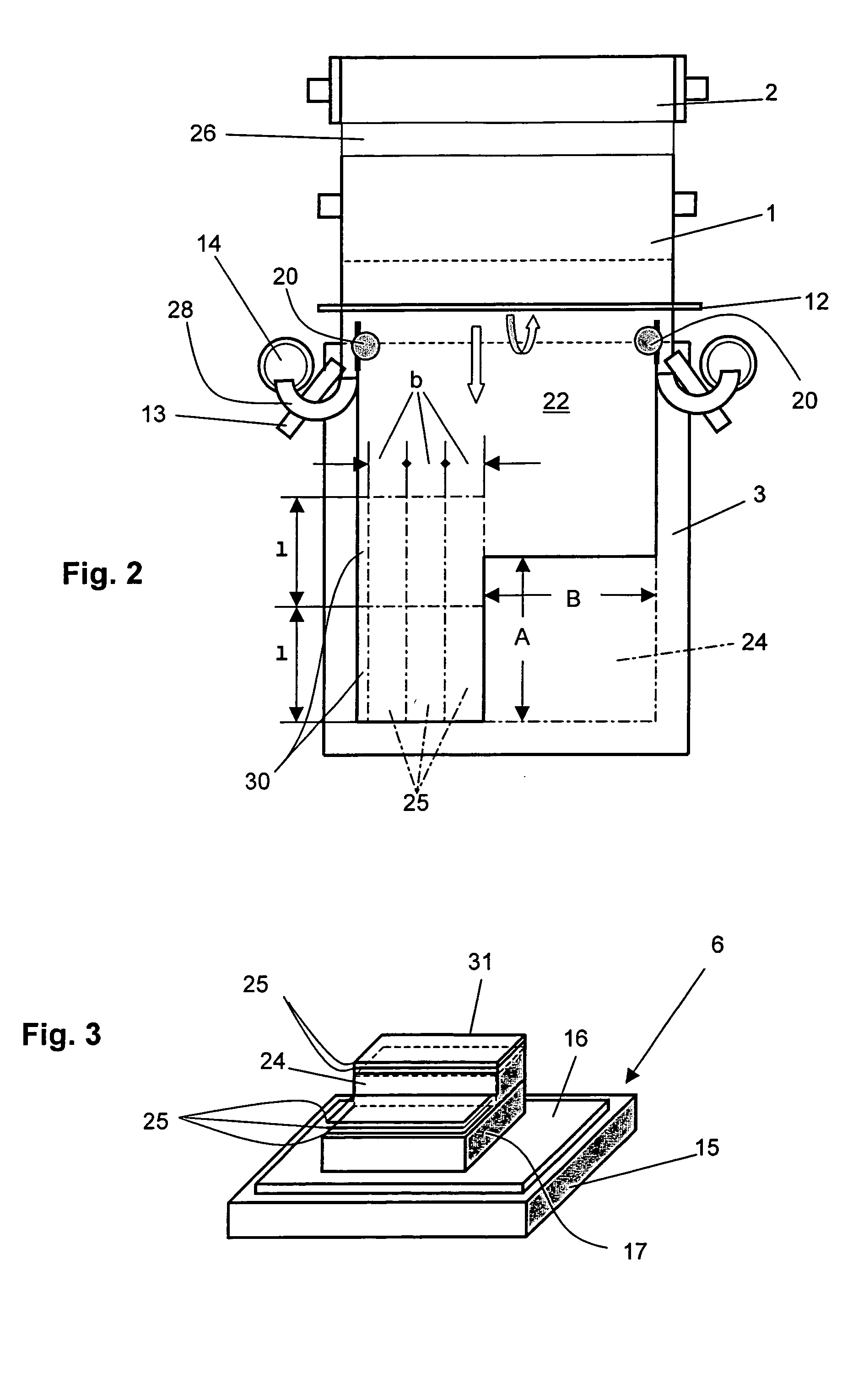
[0035] The method according to the invention which it proceeds for producing series of SMC is explained briefly on the basis of the diagram of the method according to FIGS. 1 and 2. The SMC components are produced from fibrous, reactive resin mass which is provided in the form of a virtually endless web 22 of resin-impregnated mats wound up into a supply roll 1 as the initial product. To maintain the reactivity of the synthetic resin in the web of resin-impregnated mats 22, the latter is covered with a protective film 26, which is pulled off and rolled up to form a separate roll 2 only shortly before the processing of the resin-impregnated mat. As can be seen more clearly in FIG. 2, the protective film is deflected counter to the processing direction of the resin-impregnated mat to the roll 2 via a reversing rod 12 located in the vicinity of the cutting table 3. The side edges of the web of resin-impregnated mats are unsuitable for further proces...


PUM

PropertyMeasurementUnit
Fractionaaaaaaaaaa
Fractionaaaaaaaaaa
Fractionaaaaaaaaaa

Abstract

A method and a device for the automated handling of resin-impregnated mats of differing shape and size during the production of SMC components, utilizes a suction gripper which can be manipulated multiaxially. A plurality of suction bells are distributed in a grid pattern on the suction gripper, each suction bell being actuable individually by a vacuum. The rigid suction bells, which are mounted via a flexible element, have a cup-shaped cross section with an edge that tapers to a point, and can be placed onto and form a seal with the resin-impregnated mats. Rotating brushes are provided for cleaning the suction bells. The suction gripper is combined with pivotable fixing spikes for securing the stack of mats at the uppermost layer of the stack. The suction bells can be raised and lowered to different levels via lifting cylinders and can be fixed in any desired intermediate positions by means of brakes.

Description

BACKGROUND AND SUMMARY OF THE INVENTION [0001] The invention relates to a method and a apparatus for automatically handling resin-impregnated mats during the production of SMC components. [0002] According to an article by R. Brüssel and U. Weber “SMC-Teile vollautomatisch herstellen” [Fully automatic production of SMC components], published in the journal Kunststoffe, year 79 (1989), pages 1149-1154—(hereinafter Brüssel et al.), the production of SMC components starts with a specific amount of a mixture of reactive thermosetting synthetic resin and fibers that is adapted in its weight to be appropriate for the finished component. To be precise, the adapted amount of raw material is obtained by cutting out rectangular blanks of a specific size from a fiber mat web (prepreg web) supplied in roll form and by laying the blanks together to form a stack of mats. Such a stack of mats is placed exactly in position into an opened mold of a press that is heated to a temperature at which the r...

Claims


Application Information

Patent Timeline
IPC IPC(8): B29C70/38
CPCB29C70/46B29C70/386B29C70/541
Inventor HABISREITINGER, UWENORDMANN, BERNHARD
Owner DAIMLER AG
Why Eureka
Try Eureka