
Receptacle connector with high retention force

Active Publication Date: 2015-02-26
ALLTOP ELECTRONICS SU ZHOU
View PDF3 Cites 5 Cited by
  • Summary
  • Abstract
  • Description
  • Claims
  • Application Information

AI Technical Summary

Benefits of technology

The patent text describes a new type of connector that has a very strong holding power. This is useful for ensuring that the connection is secure and reliable.

Problems solved by technology

However, the retention force between receptacle contacts and a receptacle housing of a conventional receptacle connector is not strong enough.
Hence, when the receptacle connector mates with a corresponding plug connector, if unplug force is relative high from the plug connector, the receptacle contacts of the receptacle connector are prone to being pulled to escape from the receptacle housing, further influencing the signal transmission.

Method used


Image

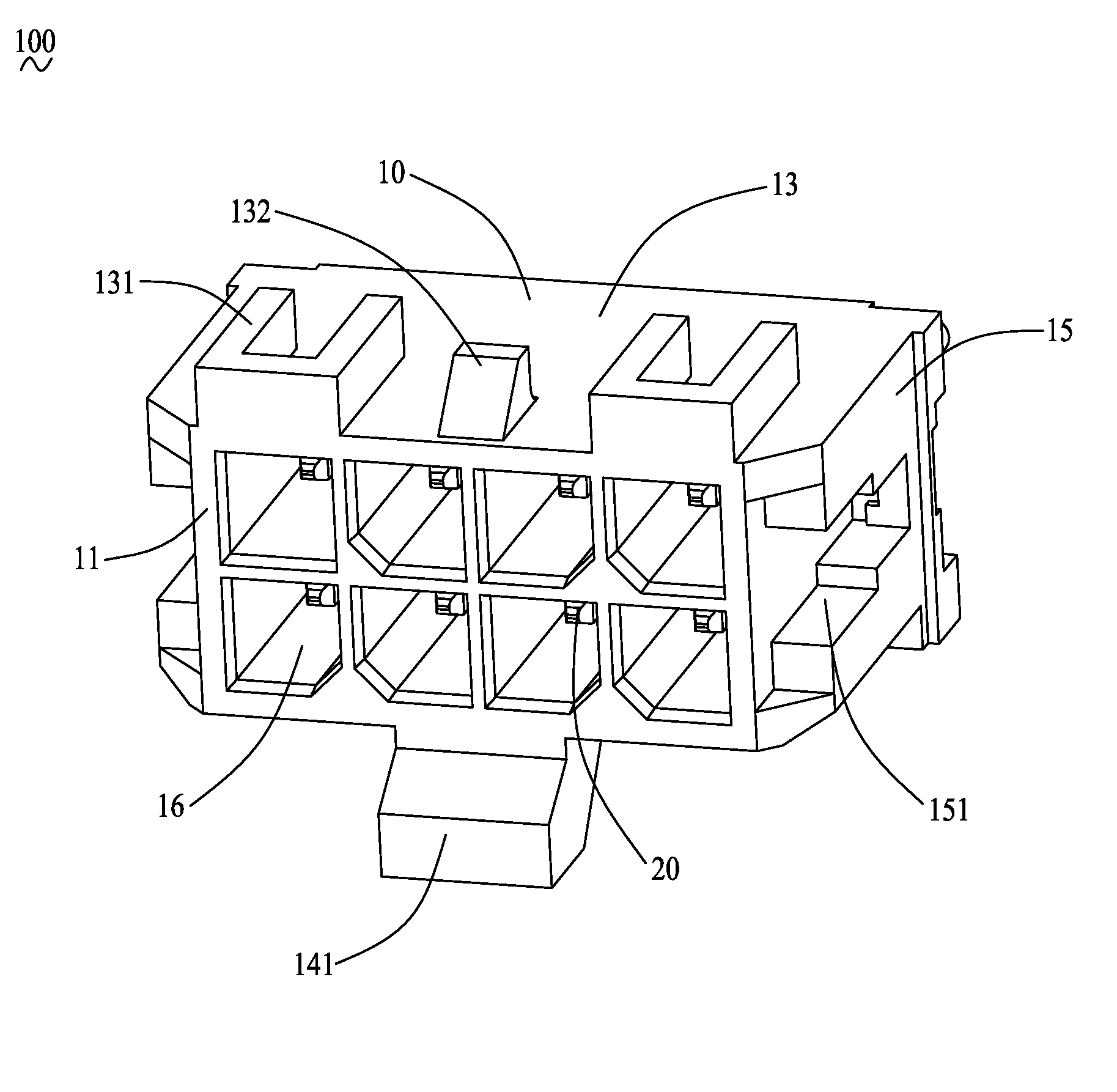
  • Receptacle connector with high retention force
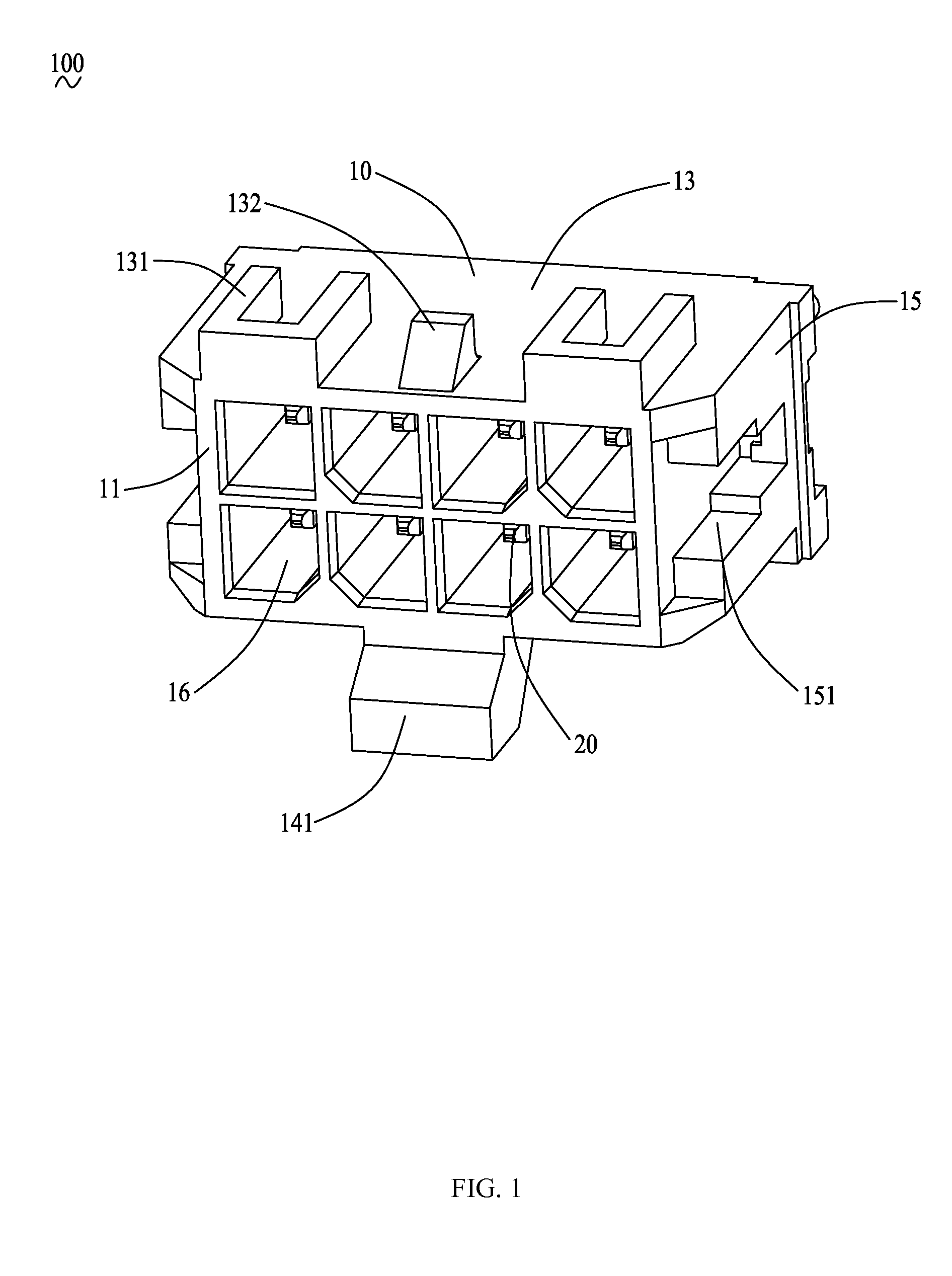
  • Receptacle connector with high retention force
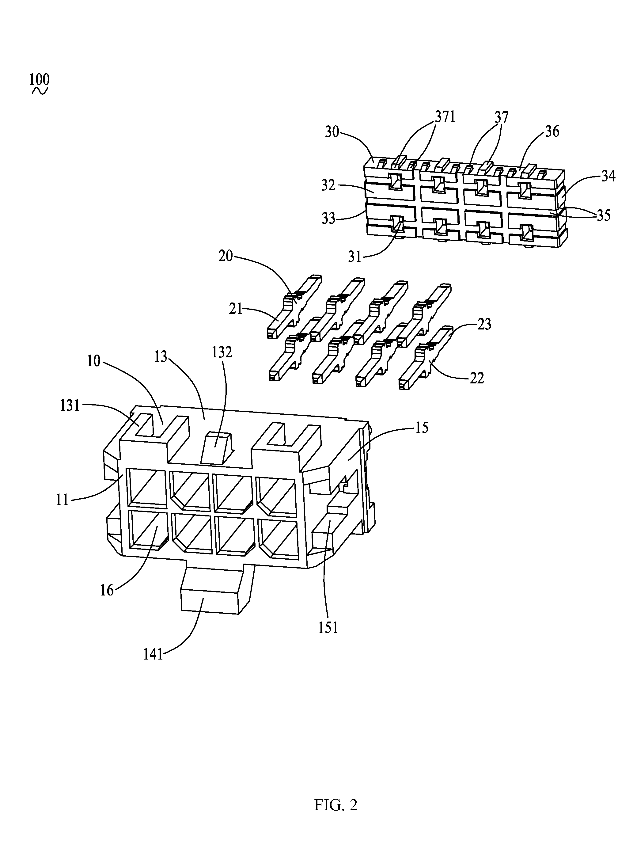
  • Receptacle connector with high retention force

Examples


Embodiment Construction

[0018]In the following description, numerous specific details are set forth to provide a thorough understanding of the present invention. However, it will be obvious to those skilled in the art that the present invention may be practiced without such specific details. In other instances, well-known circuits have been shown in block diagram form in order not to obscure the present invention in unnecessary detail. For the most part, details concerning timing considerations and the like have been omitted inasmuch as such details are not necessary to obtain a complete understanding of the present invention and are within the skills of persons of ordinary skill in the relevant art.

[0019]Reference will be made to the drawing figures to describe the present invention in detail, wherein depicted elements are not necessarily shown to scale and wherein like or similar elements are designated by same or similar reference numeral through the several views and same or similar terminology.

[0020]P...


PUM


Abstract

A receptacle connector includes an insulative housing, a number of conductive contacts, and a retainer seat. The insulative housing includes a mating face for mating with a plug connector and a mounting face opposite to the mating face. The insulative housing defines a number of contact-receiving passages penetrating from the mating face to the mounting face and a mounting recess recessed from the mounting face toward the mating face a certain distance. The conductive contacts are respectively received in the contact-receiving passages. Each conductive contact includes a contacting portion for electrically contacting the plug connector, a termination portion for electrically connecting with a Printed Circuit Board, and an intermediate portion connecting the contacting portion with the termination portion. The retainer seat is fixedly received in the mounting recess of the insulative housing.

Description

BACKGROUND OF THE INVENTION[0001]1. Field of the Invention[0002]The present invention relates to an electrical connector, more particularly to a receptacle connector mounted on a Printed Circuit Board.[0003]2. Description of Related Art[0004]With the rapid development of electronic technology, electrical connectors are widely used in electric products for exchanging information, data etc. with periphery devices. An electrical connector generally comprises an insulative housing and a plurality of conductive contacts received in the insulative housing. Solder feet of the conductive contacts extend beyond the insulative housing for being soldered to a Printed Circuit Board (PCB).[0005]To satisfy the requirements of stable signal transmission, and high transmission efficiency of the electric products, it is necessary to assure high mating stability of the electrical connectors. However, the retention force between receptacle contacts and a receptacle housing of a conventional receptacle...

Claims


Application Information

Patent Timeline
IPC IPC(8): H01R13/516
CPCH01R13/516H01R12/51H01R13/02H01R13/405H01R13/518H01R12/716H01R13/41H01R13/4367H01R13/506H01R2107/00
Inventor YU, WANG-ITAI, HUNG-CHICHENG, I-HUNGXIE, SHI-KE
Owner ALLTOP ELECTRONICS SU ZHOU
Learn More