Cover plate anchor

Inactive Publication Date: 2009-11-05
ZIMMER GUNTHER +1
View PDF16 Cites 3 Cited by
  • Summary
  • Abstract
  • Description
  • Claims
  • Application Information

AI Technical Summary

Benefits of technology

[0010]With the present invention, an anchor for light-weight building plates is provided whi

Problems solved by technology

If fixtures are to be attached to light-weight plates for example, by screws, the problem arises that the attachment means find support only in the relatively thin

Method used


Image

  • Cover plate anchor
  • Cover plate anchor
  • Cover plate anchor

Examples


Example

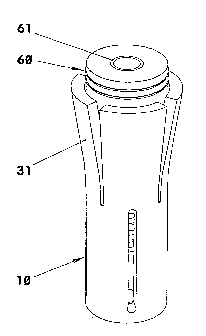
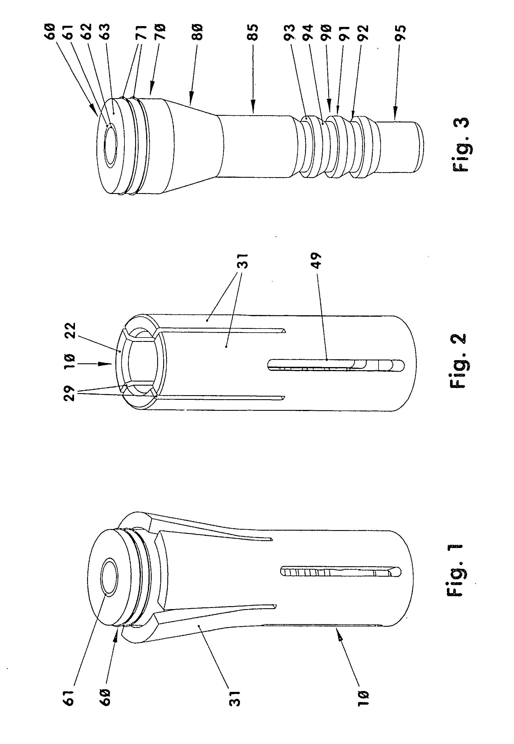
[0030]FIG. 1 shows an expansion anchor in the form which it would have after installation in a lightweight construction panel. In this embodiment, the anchor has only two parts, an expansion body (10) and a wedge body (60). Both parts (10, 60) are shown separately in FIGS. 2 and 3. The anchor according to FIG. 1 has for example a length of 35 mm. The opening drilled for mounting the anchor has for example a diameter of 8.5 mm. The diameter of the unexpanded anchor is in this design either maximally three times the core diameter of the screw to be installed via the anchor in the light-weight building plate or, maximally 2.3 times the actual diameter of the screw when threaded into the anchor.

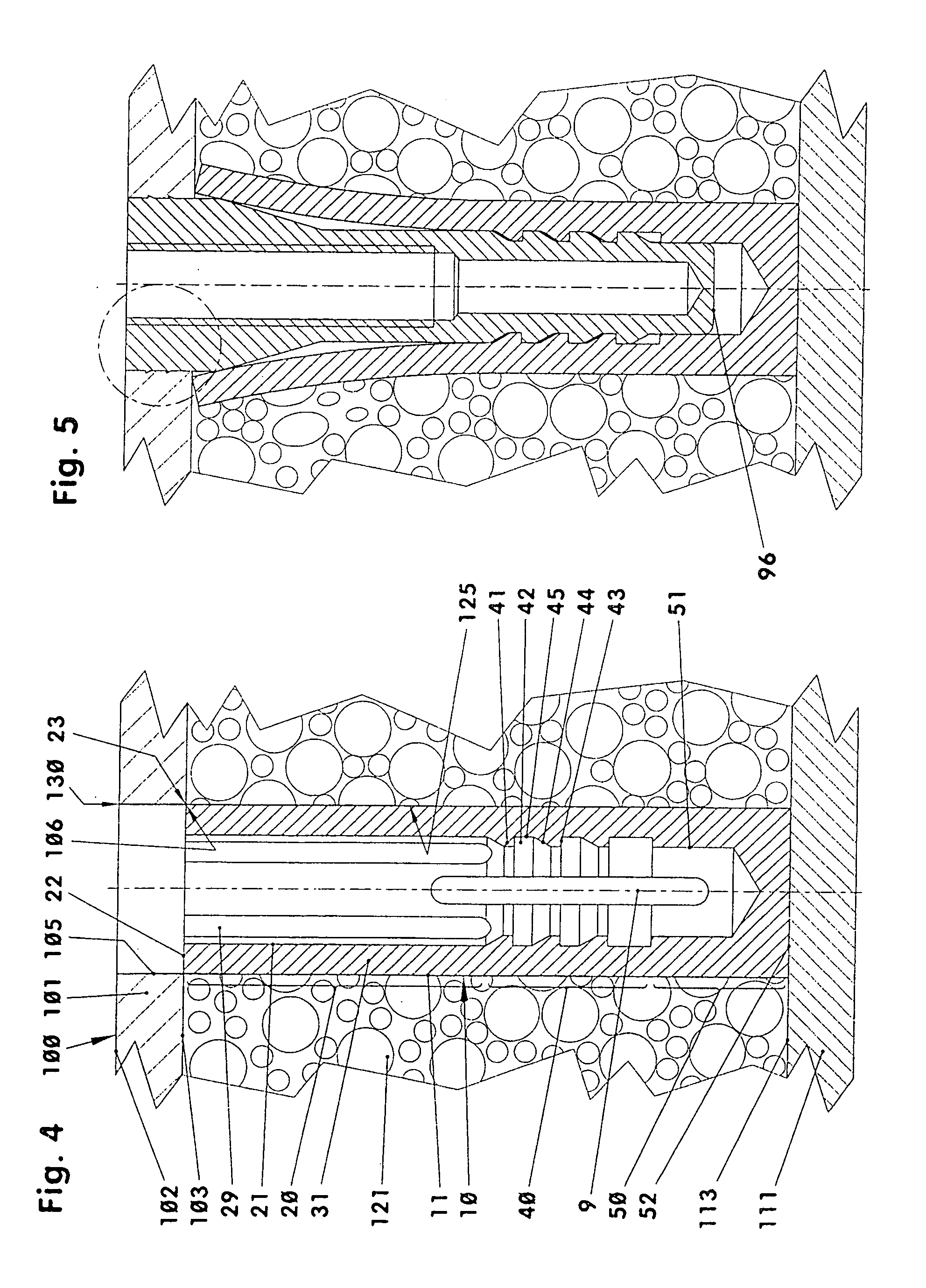
[0031]The anchor is provided for example for the mounting of fixtures to light-weight building panels (100) without walers and solid inserts, see FIG. 4. The shown lightweight building panel (100) comprises two cover plates (101, 111) and an intermediate support core (121). Each cover plate (101,...


PUM


Abstract

In an anchor for the attachment to construction panels including two cover plates and an intermediate support core layer wherein the anchor comprises an expansion body and a wedge body which inserted into the expansion body and includes an opening for screwing or pounding in a mounting means, the installed anchor is disposed in an opening of the panel which extends through the first cover plate and the intermediate support core plate. The expansion body has locking zones and engagement elements which are spreadable by wedge elements. With the anchor installed, a wedging zone spreads out the engagement elements of the expansion body behind the cover plate and the locking zones are interlocked.

Description

[0001]This is a continuation-in part application of pending international patent application PCT / DE2007 / 001867 filed Oct. 19, 2007 and claiming the priority of German patent application 10 2006 049 953.0 filed Oct. 22, 2006BACKGROUND OF THE INVENTION[0002]The invention resides in an anchor for mounting in a planar building component having first and second cover plates with an intermediate support plate, wherein the anchor includes at least a spreading body and at least one wedge body and wherein the wedge body, which is at least partially inserted into the spreading body, includes a cavity for threading or punching a mounting member into the anchor.[0003]Flat construction components are often designated as sandwich plates, honeycomb plates or light weight construction plates. All plate types used in furniture construction comprise generally cover layers of thin particle boards, medium or high density fiber boards, plywood or hard fiber boards. The sandwich plates often have an inte...

Claims


Application Information

Patent Timeline
IPC IPC(8): E04B1/38
CPCF16B13/002F16B13/144F16B13/126F16B13/0816
Inventor ZIMMER, GUNTHERZIMMER, MARTIN
Owner ZIMMER GUNTHER
Why Eureka
Try Eureka