Non-foster active impedance circuit for electrically small antennas

an active impedance circuit and antenna technology, applied in the direction of loop antennas, polarised antenna unit combinations, radiating element structure forms, etc., can solve the problems of limited application of efficient esas and often impracticality of conventional full-size antennas at these frequencies

Active Publication Date: 2018-05-01
THE UNITED STATES OF AMERICA AS REPRESENTED BY THE SECRETARY OF THE NAVY
View PDF17 Cites 6 Cited by
  • Summary
  • Abstract
  • Description
  • Claims
  • Application Information

AI Technical Summary

Problems solved by technology

Efficient ESAs are limited in application because of their small bandwidth performance.
Traditional passive impedance matching methods, when implemented at the input of an ESA, have been shown to improve this bandwidth performance, although as with any passive network are further limited by the Bode-Fano limit.
Conventional full size antennas at these frequencies are often impractical as their physical sizes are on the order of the wavelength.
Efficient, broadband ESAs are sorely needed for applications at these frequencies, which are capable of meeting or exceeding the gain-bandwidth performance dictated by the Chu Limit.

Method used


Image

  • Non-foster active impedance circuit for electrically small antennas
  • Non-foster active impedance circuit for electrically small antennas
  • Non-foster active impedance circuit for electrically small antennas

Examples


Embodiment Construction

[0018]The disclosed methods and systems below may be described generally, as well as in terms of specific examples and / or specific embodiments. For instances where references are made to detailed examples and / or embodiments, it should be appreciated that any of the underlying principles described are not to be limited to a single embodiment, but may be expanded for use with any of the other methods and systems described herein as will be understood by one of ordinary skill in the art unless otherwise stated specifically.

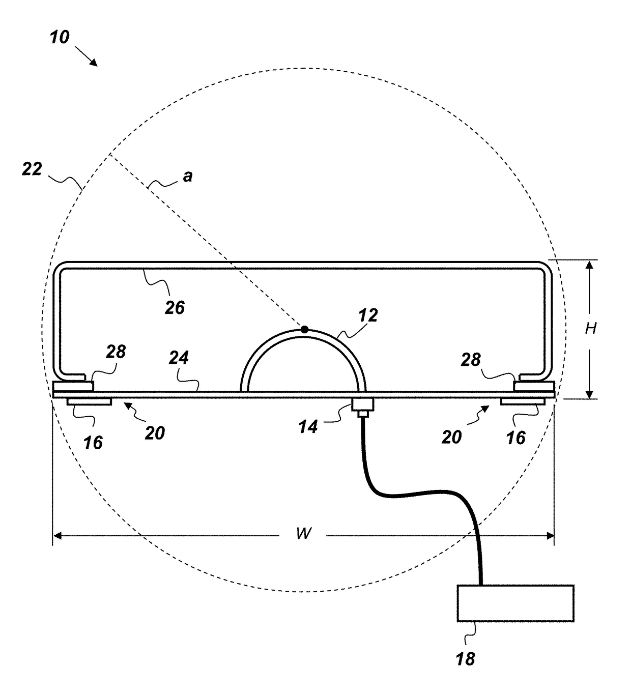
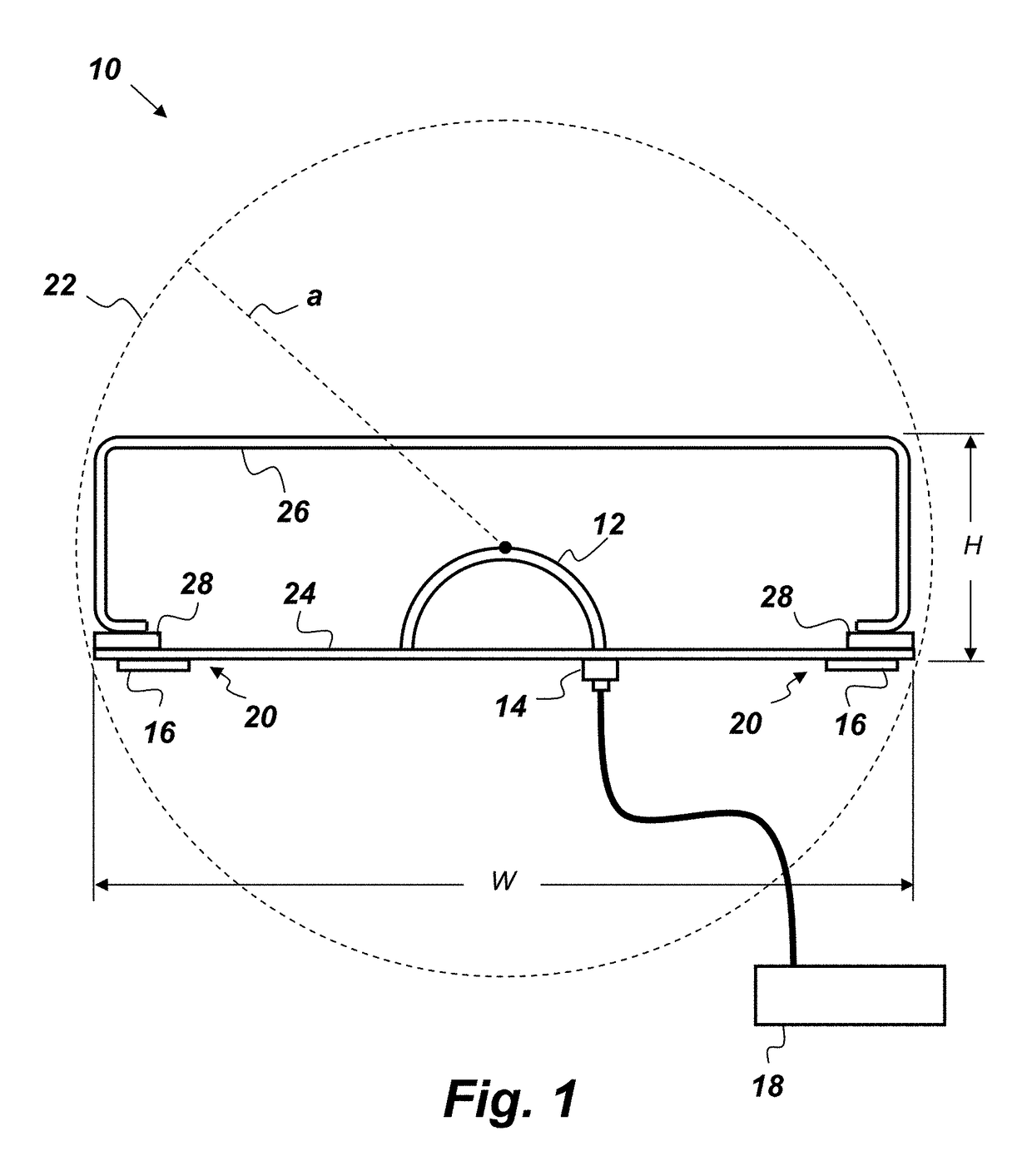
[0019]FIG. 1 is a side-view illustration of an electrically small antenna (ESA) 10 that comprises, consists of, or consists essentially of a driven element 12, an input feed 14, and a non-Foster circuit 16. The driven element 12 may be coupled to the input feed 14 and the input feed 14 may be configured to be connected to a receiver 18. The non-Foster circuit 16 has a negative impedance and may be configured to actively load the ESA 10 at a location 20 on the antenna...


PUM


Abstract

An antenna comprising: a driven element; an input feed coupled to the driven element wherein the input feed is configured to be connected to a receiver; a non-Foster circuit having a negative impedance, wherein the non-Foster circuit is configured to actively load the antenna at a location on the antenna other than at the input feed; and wherein the antenna fits within an imaginary sphere having a radius a, and wherein the product ka is less than 0.5, where k is a wave number.

Description

CROSS-REFERENCE TO RELATED APPLICATION[0001]This application is a continuation-in-part of prior U.S. application Ser. No. 13 / 494,111, filed 12 Jun. 2012, titled “Electrically Small Circularly Polarized Antenna” (Navy Case #101173), which application is hereby incorporated by reference herein in its entirety.FEDERALLY-SPONSORED RESEARCH AND DEVELOPMENT[0002]The United States Government has ownership rights in this invention. Licensing and technical inquiries may be directed to the Office of Research and Technical Applications, Space and Naval Warfare Systems Center, Pacific, Code 72120, San Diego, Calif., 92152; voice (619) 553-5118; ssc_pac_t2@navy.mil. Reference Navy Case Number 102794.BACKGROUND OF THE INVENTION[0003]The invention disclosed herein relates to the field of Electrically Small Antennas (ESAs). The performance of ESAs are dictated by the Chu Limit, in which the gain-bandwidth product cannot exceed this fundamental limit. Efficient ESAs are limited in application becaus...

Claims


Application Information

Patent Timeline
Patent Type & Authority Patents(United States)
IPC IPC(8): H01Q1/24H03H11/00H01Q7/00H01Q21/24H01Q5/35H01Q1/36
CPCH01Q1/36H01Q5/35H03H11/00H01Q21/24H01Q7/005
Inventor CHIEH, JIA-CHI SAMUELXU, LURYU, ALBERTROCKWAY, JOHN D.ARCEO, DIANACHURCH, JUSTIN A.
Owner THE UNITED STATES OF AMERICA AS REPRESENTED BY THE SECRETARY OF THE NAVY
Why Eureka
Try Eureka