Control device for controlling facility equipment

a technology for controlling equipment and facilities, applied in lighting and heating equipment, instruments, heating types, etc., can solve the problems of impaired comfort of users and severe impairment of users' comfort, and achieve the effect of not suppressing energy consumption, hardly impaired comfort of users, and certain comfort levels of users

Active Publication Date: 2018-05-08
DAIKIN IND LTD
View PDF28 Cites 0 Cited by
  • Summary
  • Abstract
  • Description
  • Claims
  • Application Information

AI Technical Summary

Benefits of technology

[0021]In the control device according to the first aspect of the present invention, the energy consumption is suppressed most strongly in the first time slot in which the index that includes a factor of an energy unit price approaches to its peak. Since the energy consumption is not suppressed in the other time slots as strongly as in the first time slot, it is highly likely that a certain level of comfort of the user is maintained in the first time slot. As a result, the comfort of the user is hardly impaired even if strong energy adjustment control is executed in the time slot in which the index approaches to its peak.
[0022]In the control device according to the second aspect of the present invention, in the second time slot prior to the time slot in which the index that includes a factor of an energy unit price approaches to its peak, the intensity of the energy adjustment control becomes lowest among the three types of time slots. Therefore, it is highly likely that a certain level of comfort of user is maintained when the time slot in which the index approaches to its peak starts. As a result, the comfort of the user is hardly impaired even if strong energy adjustment control is executed in the time slot in which the index approaches to its peak. Furthermore, since the intensity of the energy adjustment control executed in the time slot subsequent to the time slot in which the index approaches to its peak is equal to or lower than the intensity of the energy adjustment control in the time slot in which the index approaches to its peak, flexible energy adjustment control is accomplished according to the degree of the comfort of the user.
[0023]In the control device according to the third aspect of the present invention, strong energy adjustment control is executed in the time slot in which the energy cost is predicted to reach its peak. As a result, the energy adjustment control for reducing the energy cost is readily accomplished with assuring the comfort.
[0024]In the control device according to the fourth aspect of the present invention, the energy consumption is not suppressed in the time slot prior to the time slot in which the index that includes a factor of the energy unit price approaches to its peak. Thus, the comfort of the user is readily assured in the time slot in which the index approaches to its peak.
[0025]In the control device according to the fifth aspect of the present invention, it is possible to execute the energy adjustment control after the possible amount of energy consumption adjustment is ascertained in advance.
[0026]In the control device according to the sixth aspect of the present invention, a plurality of conditions are prepared and the user selects a condition for the energy adjustment control by him / herself. Thus, the energy adjustment control which reflects the user's demand is readily available.

Problems solved by technology

However, in cases where the energy unit price is notified, if the users place excessive importance on reducing energy costs, comfort of the users may be impaired.
Particularly, in cases where the energy consumption is suppressed excessively, the comfort of the users may be severely impaired in the peak hour of the energy unit price, when the energy consumption is encouraged to be suppressed most.

Method used


Image

  • Control device for controlling facility equipment
  • Control device for controlling facility equipment
  • Control device for controlling facility equipment

Examples


first embodiment

[0047]An energy management system 100 according to a first embodiment of the present invention shall be described below with reference to the drawings.

[0048](1) OVERALL CONFIGURATION OF ENERGY MANAGEMENT SYSTEM 100

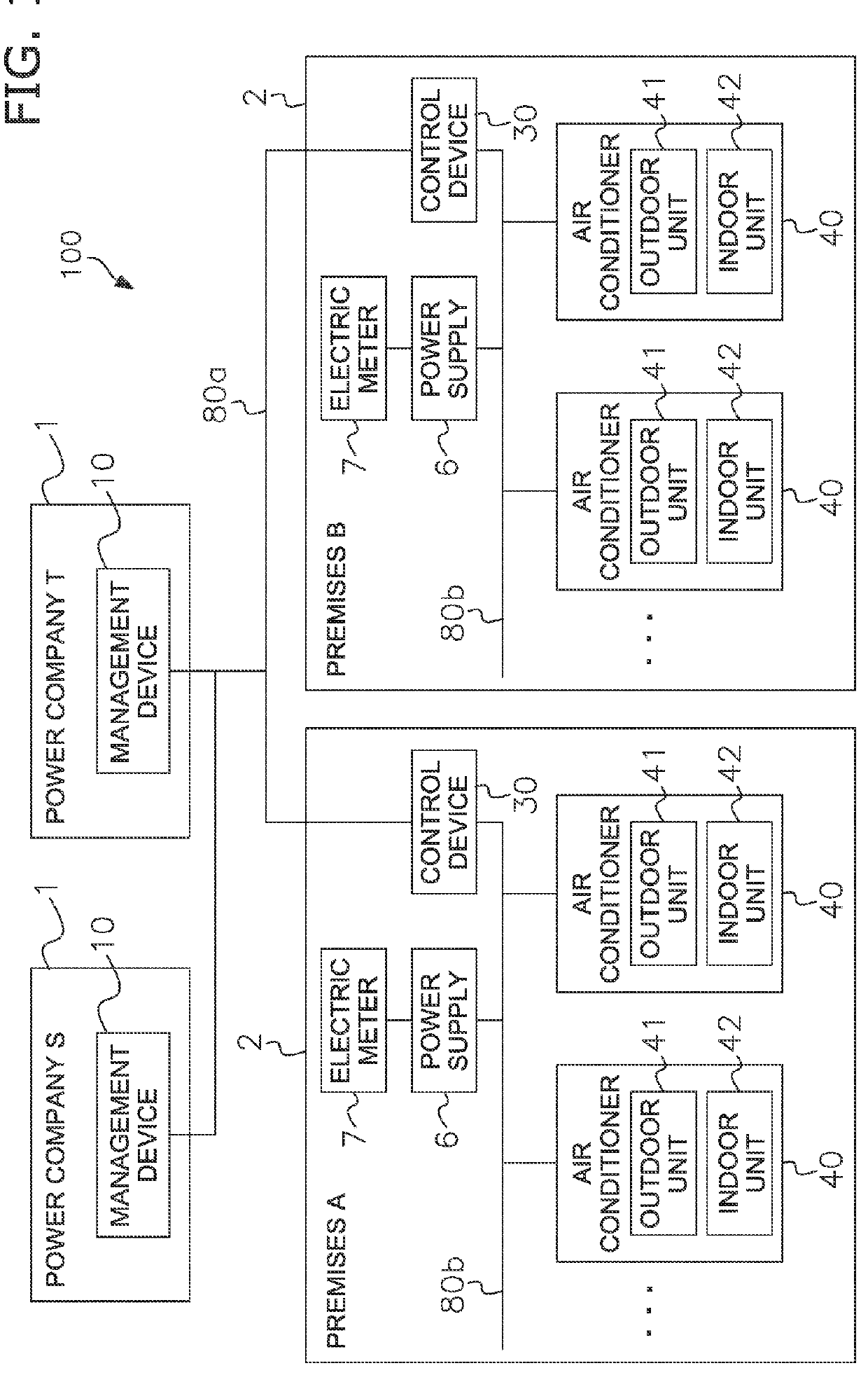
[0049]FIG. 1 shows the energy management system 100 according to the present embodiment. In this energy management system 100, power companies S, T supply energy to premises A, B. The premises A, B are structures, such as office buildings, tenant buildings, factories, ordinary residences, or the like, in which one or a plurality of pieces of facility equipment is situated. In FIG. 1, only two premises A, B are illustrated as premises that are supplied with energy by the power companies, but the number of premises is not limited to two. Moreover, although two power companies S. T are illustrated, the number of power companies is not limited to two. The number of power companies may be more than 2 or just one.

[0050]The power companies S, T have management devices 10, 10. The...

modification examples

(5) MODIFICATION EXAMPLES

(5-1) Modification Example 1A

[0167]The method for delivering the unit price information from the management device 10 of the power supplying company is not limited to that mentioned above. For example, a method in which the unit price information is delivered by fax over phone lines would also be acceptable. In this case, the control device 30 would receive the unit price information contained in the faxed document, by the input of the user through the input unit 33.

modification example 1b

(5-2) Modification Example 1B

[0168]The intensity storage area 35b may store values such as the maximum permissible energy consumption, the permissible amounts of energy adjustment, the permissible numbers of air conditioners 40, 40 . . . in utilization, and the like, instead of, or in addition to, the maximum permissible operating capacity for different types of time slot. Examples of information stored in the intensity storage area 35b are shown in FIG. 13 (a) to (c).


PUM


Abstract

The control device controls facility equipment and includes a receiving unit, first and second decision units and an adjustment control unit. The receiving unit receives time-of-use unit price information of an energy supplied to the facility equipment. The first decision unit decides a first time slot in which an index that includes a factor of an energy unit price approaches a peak in a first period based on the time-of-use unit price information. The second decision unit decides a second time slot prior to the first time slot and a third time slot subsequent to the first time slot in the first period. The adjustment control unit executes an energy adjustment control to adjust an energy consumption of the facility equipment so that an amount of suppression of the energy consumption is higher in the first time slot than in the second and the third time slots.

Description

CROSS-REFERENCE TO RELATED APPLICATIONS[0001]This U.S. National stage application claims priority under 35 U.S.C. § 119(a) to Japanese Patent Application No. 2011-116755, filed in Japan on Jun. 30, 2011, the entire contents of which are hereby incorporated herein by reference.TECHNICAL FIELD[0002]The present invention relates to a control device for controlling facility equipment.BACKGROUND ART[0003]Recent years, it is becoming increasingly common that energy suppliers encourage a plurality of premises of users to suppress the energy consumption in the time of high energy demand for more efficient operation of energy supply facilities.[0004]For example, in actual practice, energy suppliers adopt a scheme to notify the premises of time-of-use energy unit price (JP-A No. 2007-139213). This scheme motivates the users to suppress the energy consumption in the time of high energy demand.SUMMARYTechnical Problem[0005]However, in cases where the energy unit price is notified, if the users ...

Claims


Application Information

Patent Timeline
Patent Type & Authority Patents(United States)
IPC IPC(8): G05D3/12F24F11/00G05B13/02H02J3/14
CPCF24F11/30G05B13/02H02J3/14Y04S20/224Y04S20/244F24F11/62H02J2003/146Y02B70/3225Y02B70/3275Y04S20/222F24F11/46H02J2310/64H02J2310/12H02J2310/14Y02B70/30Y04S50/10Y04S20/242F24F11/64F24F11/47F24F11/523
Inventor KAWAI, SEIJIKINUGASA, NANAE
Owner DAIKIN IND LTD
Why Eureka
Try Eureka