
Thread rolling head

a threaded rolling head and thread technology, applied in the field of threaded rolling heads, can solve the problems of displacement insufficient precision of positioning insufficient manual rotation of the profile roller, so as to achieve the maximum adjustment range of the threaded rolling head

Active Publication Date: 2018-05-15
LMT FETTE WERKZEUGTECHN
View PDF19 Cites 0 Cited by
  • Summary
  • Abstract
  • Description
  • Claims
  • Application Information

AI Technical Summary

Benefits of technology

This patent describes a thread rolling head that allows for precise adjustment of the spacing of rollers even with tools having multiple profile rollers. The adjustment is possible through a simple and easy-to-use adjustment element, which ensures the rollers remain secure in their positions and prevents unintentional displacement. The display apparatus notes the changes in the roller spacing caused by the relative rotation of the housing parts, making it simple to achieve the desired adjustment. The threaded spindle and slide block mechanism are also used to achieve accurate and reliable positioning of the rollers. The guide displays the starting position of the rollers and allows for complete adjustment of their spacing. The technical effects of the present invention include improved efficiency, accuracy, and reliability of the thread rolling head.

Problems solved by technology

However, manual rotation often does not provide sufficient fine positioning of the profile rollers.
A further provided scale can lead to confusion because with different rolling head positions, there is positioning to a greater or lesser extent.
There is also the danger that after manual rotation and in the course of subsequent clamping, there is an undesired rotation of the housing parts, and thus displacement of the profile rollers.
The device described in German document DE 9002822 U1 is constructively elaborate and likewise does not attain a defined positioning in a sufficiently precise manner.
In such a design, however, it is disadvantageous that one threaded pin must always be loosened first and then re-tightened in order to be able to adjust with the other threaded pin in the other direction.

Method used


Image

  • Thread rolling head
  • Thread rolling head
  • Thread rolling head

Examples


Embodiment Construction

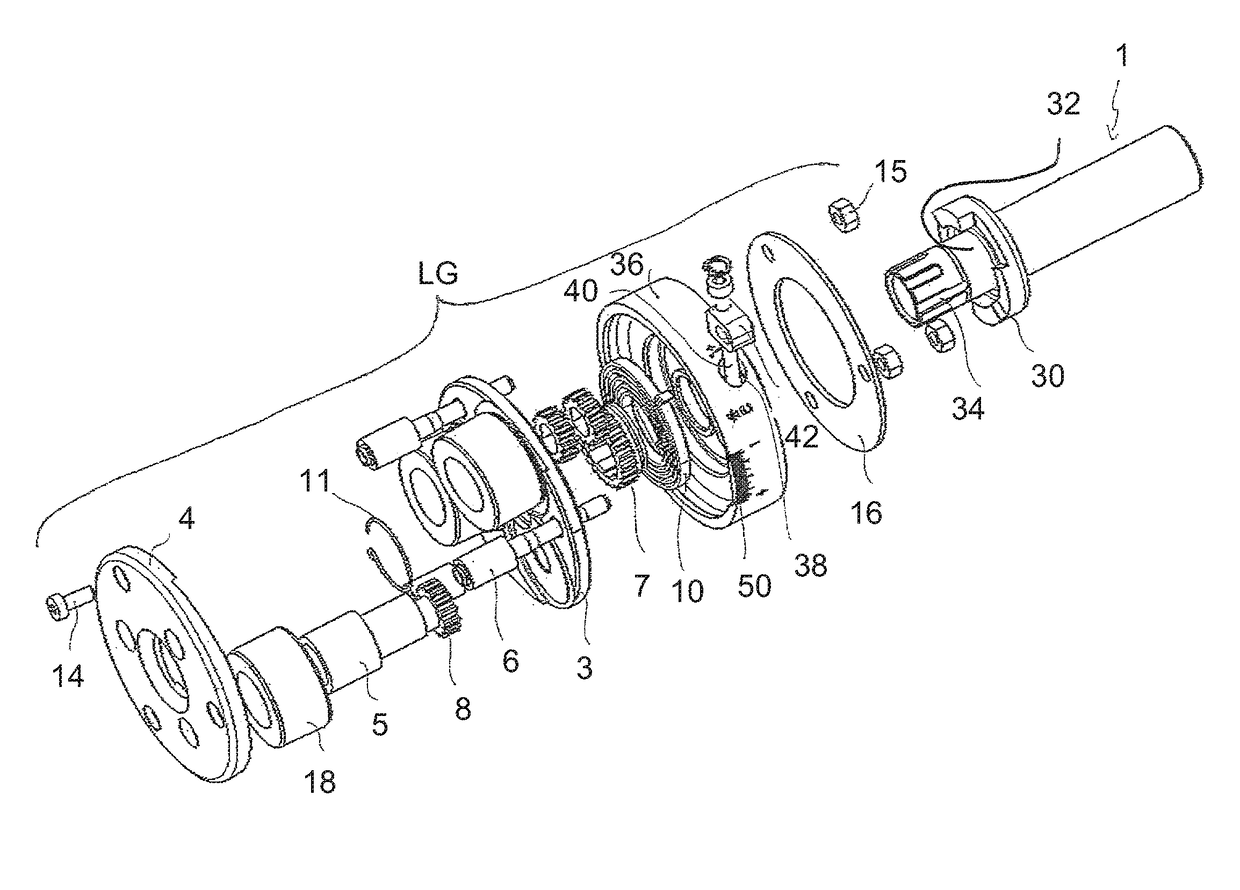
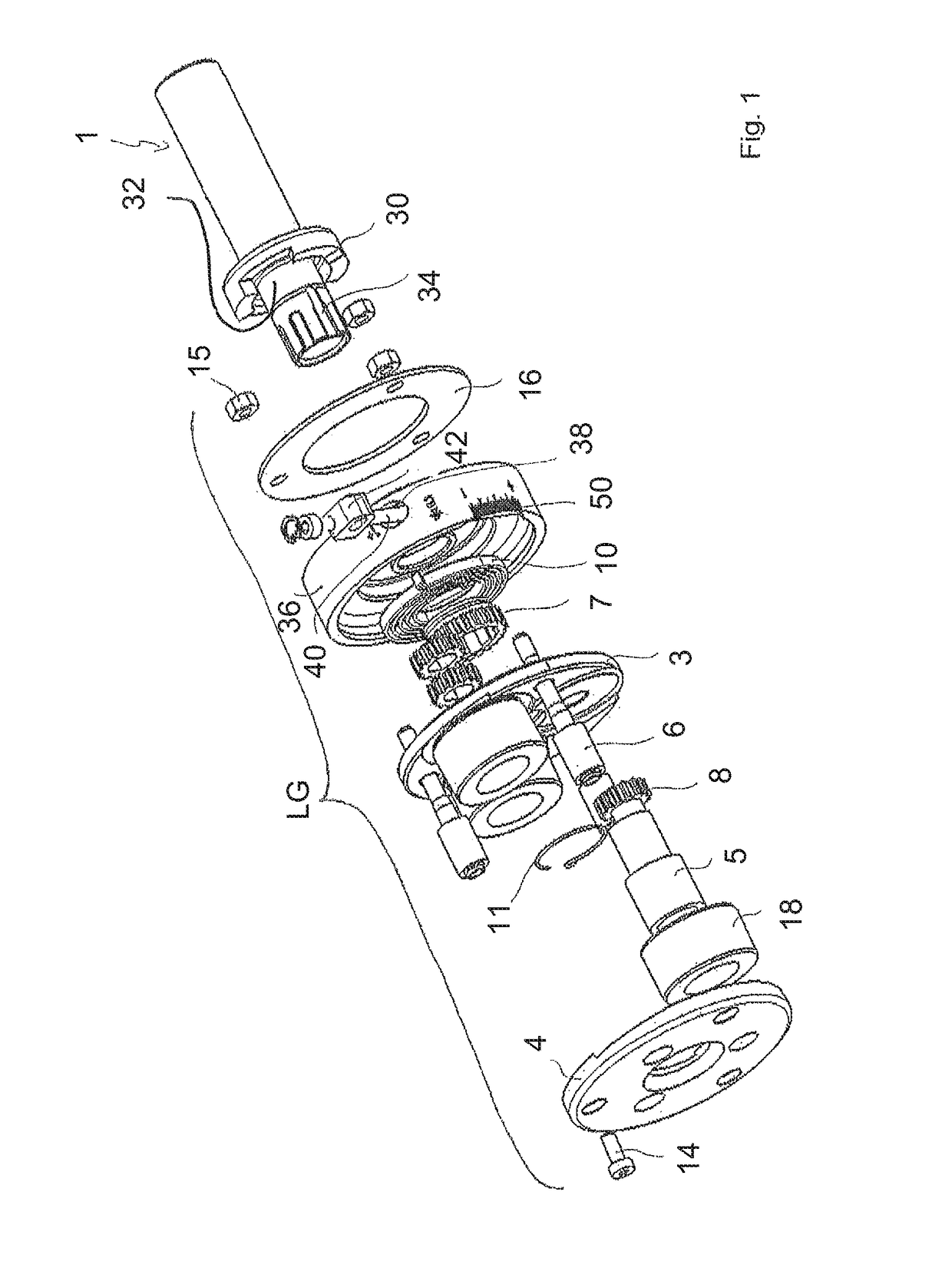
[0039]FIG. 1 shows a thread rolling head according to an embodiment of the invention, here an axial thread rolling head. It has a bearing housing LG and a shank 1. The shank 1 can be mounted, for example, in a numerically-controlled tool machine. It has a coupling section 30 and a cylindrical bearing section 32. In addition, it has a splined section 34. In the example shown there are three profile rollers 18 in the bearing housing, each mounted on an eccentric shaft 5. The ends of the eccentric shafts 5 are seated in corresponding bore holes of a front plate 4 and an intermediate plate 3. The two plates 3, 4 are held separated by distance bolts 6. The distance bolts 6 are screwed to the front plate 4 using screws 14. A threaded opposing end section of the distance bolts 6 extends through corresponding bore holes in the intermediate plate 3.

[0040]The profile rollers 18 are mounted rotatably on the eccentric shafts 5, which are flattened on the rear ends, wherein the flattened end in ...


PUM


Abstract

A thread rolling head includes a bearing housing, in which at least two profile rollers, preferably at least three, are each rotatably mounted on an eccentric shaft. A shank is coupled to the housing, and adjacent profile rollers delimit an insertion section into which a workpiece can be longitudinally inserted. The bearing housing includes two housing parts rotatable relative to each other to change the spacing between the profile rollers. An adjustment element interacts with one of the two housing parts and can rotate about the longitudinal axis thereof. Rotation of the adjustment element in a first direction causes rotation of the two housing parts in a third rotational direction, while its rotation in the second direction causes rotation of the housing parts in a fourth rotational direction counter to the third rotational direction. A display apparatus displays a change of the spacing between the profile rollers.

Description

CROSS-REFERENCE TO RELATED APPLICATION[0001]This application claims priority to EP 13 197 739.9, filed Dec. 17, 2013, the content of which is incorporated herein in its entirety by reference.FIELD OF THE DISCLOSURE[0002]The disclosure relates in general to a thread rolling head.BACKGROUND[0003]Thread rolling heads can be, for example, axial thread rolling heads or radial thread rolling heads. They can have, for example, three profile rollers uniformly distributed about an insertion section. A workpiece, cylindrical for example, can be inserted in the longitudinal direction into the insertion section. With axial thread rolling heads, machining (that is, forming the threads) on the workpiece occurs in the course of insertion into the insertion section. With radial thread rolling heads, the profile rollers for machining are positioned radially onto the workpiece after the insertion of the workpiece. Generally, there is an opening mechanism with which the profile rollers can be displace...

Claims


Application Information

Patent Timeline
Patent Type & Authority Patents(United States)
IPC IPC(8): B21H3/04
CPCB21H3/046B21H3/044B21H3/048B21H3/042
Inventor GUTSCHE, CHRISTIANJANKE, STEFANLIENAU, RAPHAEL
Owner LMT FETTE WERKZEUGTECHN
Learn More