Cold roll forming method for reducing a diameter of a metal pipe, and a metal pipe product having its diameter reduced by such method

Inactive Publication Date: 2006-09-14
ISHIKAWA TSUYOSHI +5
View PDF5 Cites 0 Cited by
  • Summary
  • Abstract
  • Description
  • Claims
  • Application Information

AI Technical Summary

Benefits of technology

[0010] It is therefore one object of the present invention to provide a cold-working method, more specifically, a cold roll forming method, that provides an easy and reliable manner for cold roll forming raw metal pipes by using sets of diameter-reducing rolls, without having to increase a number of roll stands used, wherein the method may be used to roll a raw metal pipe so that it can have a reduction in terms of its diameter, or to roll the raw metal pipe so that it can have a pattern of alternating grooves and ridges on inner and / or outer circumferential surface(s) thereof while at the same time having reduction in terms of its diameter, or to roll a double pipe including an outer pipe and an inner pipe so that it can have a reduction in terms of its diameter.

Problems solved by technology

The above mentioned methods may serve their respective cold-working or cold-roll-forming purposes, but any of the methods has problems in that a machine that is used to implement this method is designed for particular applications, there are restrictions on size (angle) of a steel pipe that can be cold-worked or rolled, a number of roll stands must be increased, and the like.

Method used


Image

  • Cold roll forming method for reducing a diameter of a metal pipe, and a metal pipe product having its diameter reduced by such method
  • Cold roll forming method for reducing a diameter of a metal pipe, and a metal pipe product having its diameter reduced by such method
  • Cold roll forming method for reducing a diameter of a metal pipe, and a metal pipe product having its diameter reduced by such method

Examples


embodiment 1

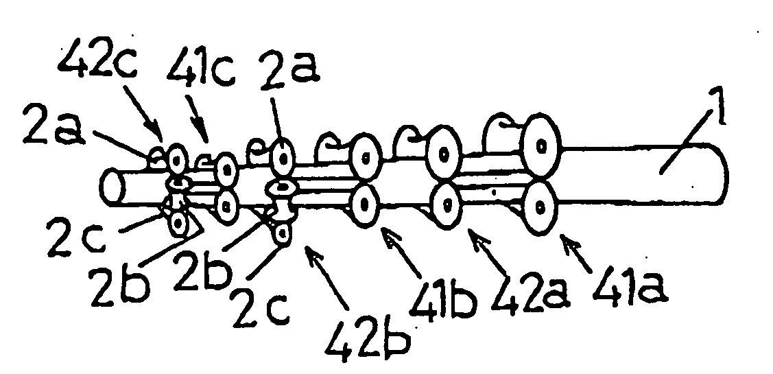
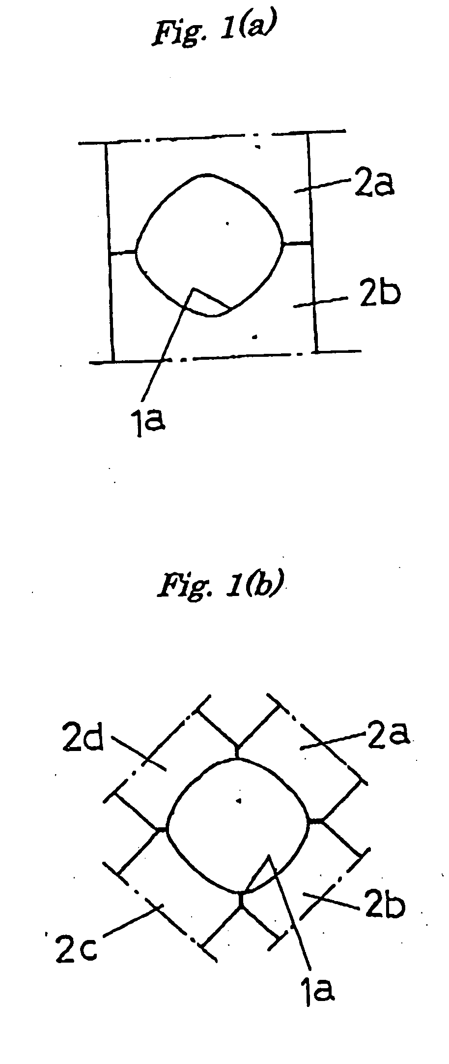
[0081] A raw pipe 1 that is subject to a diameter-reducing process is made of steel, and is originally formed into a round shape having an outer diameter of 216.3 mm. As an initial step, round steel pipe 1 may be passed through a set of pre-forming rolls 2a and 2b so that it can be formed into an intermediate steel pipe 1a having a rectangular cross section (FIG. 1 (a)).

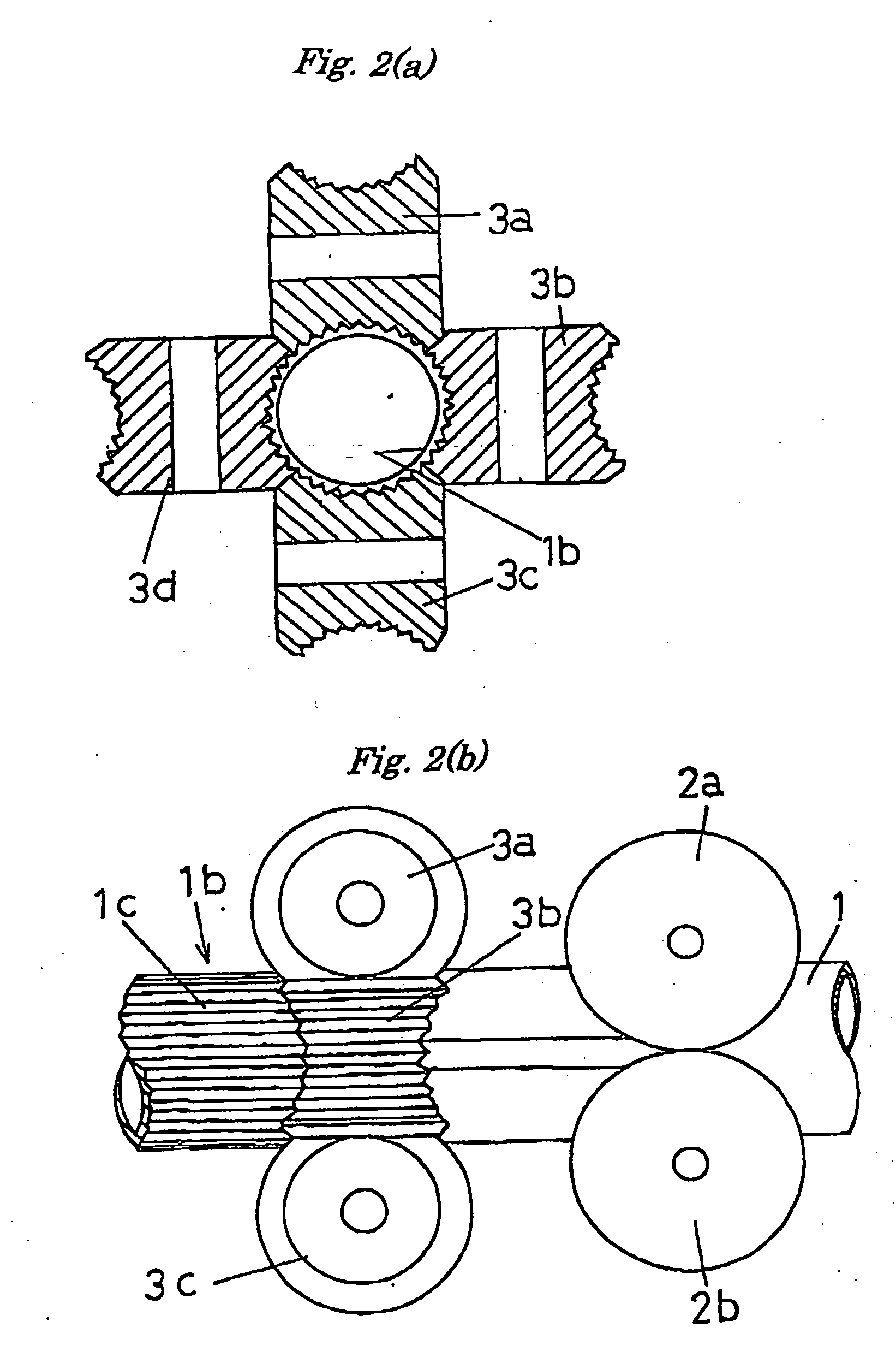
[0082] Then, the intermediate steel pipe 1a may be passed through a set of diameter-reducing rolls 3a, 3b, 3c and 3d so that it can be formed into a round steel pipe 1b having a reduced diameter (FIGS. 2 (a) and (b)).

[0083] During the diameter-reducing process, a hydraulically-operated cylinder 4 may be operated so that its piston rod 5 can be moved forward in a direction of arrow 6 in FIG. 4, thereby moving the round steel pipe 1 in that direction. There are cases in which a size, particularly a length, of the hydraulically-operated cylinder 4 should be reduced into a particular size or length for some reasons. In...

embodiment 2

[0088] A raw pipe 7 is also made of steel, and has a round shape. Different from the preceding embodiment, the raw pipe 7 is a double pipe including an additional pipe 8 made of synthetic resin that is inserted into the raw steel pipe 7. A diameter reducing process includes a pre-forming step, followed by a diameter reducing step, like in the preceding embodiment, but differs in that each of rolls 3a, 3b, 3c, 3d in a set of diameter-reducing rolls has no pattern of ridges and grooves on its circumferential surface.

[0089] By passing the raw steel pipe 7 through the pre-forming step and then through the diameter reducing step, a double pipe 10 may be obtained, including the outer steel pipe 7 and the inner synthetic resin pipe 8 as shown in FIG. 3 (b).

[0090] Specifically, when the raw steel pipe 7 is passed through the diameter reducing step, it may have a reduction in terms of its diameter. In the double pipe 10 thus obtained, the outer steel pipe 7 and the inner synthetic resin pi...

embodiment 3

[0091] A steel pipe “STKM13A” (carbon steel pipe for machine structural purposes) as specified in relevant JIS specifications is used as a raw steel pipe. The raw steel pipe has an outer diameter of 60.5 mm and a wall thickness of 2.9 mm.

[0092] This embodiment uses a process shown in FIG. 5 (b). A diameter reducing process may be performed by passing the raw steel pipe through a set of two pre-forming rolls so that it can be formed into an intermediate steel pipe having an elliptical cross-sectional shape, and then by passing the intermediate steel pipe through a set of two diameter-reducing rolls so that it can be formed into a final steel pipe having a reduction in terms of its diameter. The final steel pipe has an outer diameter of 58.2 mm, which corresponds to a diameter reduction rate of 3.8%.


PUM

PropertyMeasurementUnit
Fractionaaaaaaaaaa
Fractionaaaaaaaaaa
Thicknessaaaaaaaaaa

Abstract

A cold roll forming method for reducing a diameter of a metal pipe and a metal pipe product having a diameter reduced by such a method are disclosed, wherein the method includes: passing a raw metal pipe through a set of pre-forming rolls so that it can be pre-formed into an intermediate metal pipe having an elliptical, elongated circular or rectangular cross-sectional shape; and then passing the intermediate metal pipe through a set of diameter-reducing rolls disposed on a downstream side of the set of pre-forming rolls so that it can have its outer circumferential length reduced to be smaller than an outer peripheral length of the raw metal pipe, while at the same time being re-formed into a circular cross-sectional shape or any other cross-sectional shape different from the cross-sectional shape of the intermediate metal pipe.

Description

[0001] This application is a continuation of U.S. application Ser. No. 10 / 381,341, filed Mar. 25, 2003, which was the National Stage of International Application No. PCT / JP01 / 08310, filed Sep. 25, 2001.BACKGROUND [0002] 1. Technical Field [0003] The present invention relates to a cold roll forming method for reducing a diameter of a metal pipe, and a metal pipe product having its diameter reduced by such method. More particularly, the present invention relates to a metal pipe so formed that its diameter can be reduced by the cold roll forming process. [0004] 2. Prior Art [0005] There are a number of conventional cold roll forming methods, more specifically, cold diameter-reducing methods, whereby a diameter of a metal pipe may be reduced. These methods are briefly described below. [0006] One method is provided for cold-reducing a steel pipe by using a 3-roll reducer (Japanese patent application as published under No. H7 (1995)-51707). This method is specifically designed to eliminat...

Claims


Application Information

Patent Timeline
IPC IPC(8): B21B13/12B21C1/22B21C3/08B21C37/20B21D15/02B21H1/20B21H7/18
CPCB21B13/10B21B17/00B21C1/22B21C1/27B21C3/08B21C37/202B21D15/02B21H1/20B21H7/187F16L9/02B21C37/06
Inventor ISHIKAWA, TSUYOSHITSUKADA, YOSHIYASUZUKI, RYOICHIISHIKAWA, AKIHIROISHIKAWA, MOTOYOSHIISHIKAWA, JUN
Owner ISHIKAWA TSUYOSHI
Why Eureka
Try Eureka