Arterial embolic filter deployed from catheter

Inactive Publication Date: 2006-08-01
ADVANCED VASULAR TECH +1
View PDF6 Cites 69 Cited by
  • Summary
  • Abstract
  • Description
  • Claims
  • Application Information

AI Technical Summary

Benefits of technology

[0017]The deployment method is an important advance. The action of the paired struts is far superior to the action of a single strut, because when a pair of struts is connected distally, the distal movement of the

Problems solved by technology

In addition, the high velocity jetting effect from an aortic perfusion cannula may also cause dislodging of emboli.
Emboli that flow to the brain may cause a stroke or neurological deficit.
First, there is a possibility that they may not form a tight seal against the aortic wall due to blood flow following the path of least resistance and flowing around the filter, between the filter and the arterial wall, thus possibly a

Method used


Image

  • Arterial embolic filter deployed from catheter
  • Arterial embolic filter deployed from catheter
  • Arterial embolic filter deployed from catheter

Examples


first embodiment

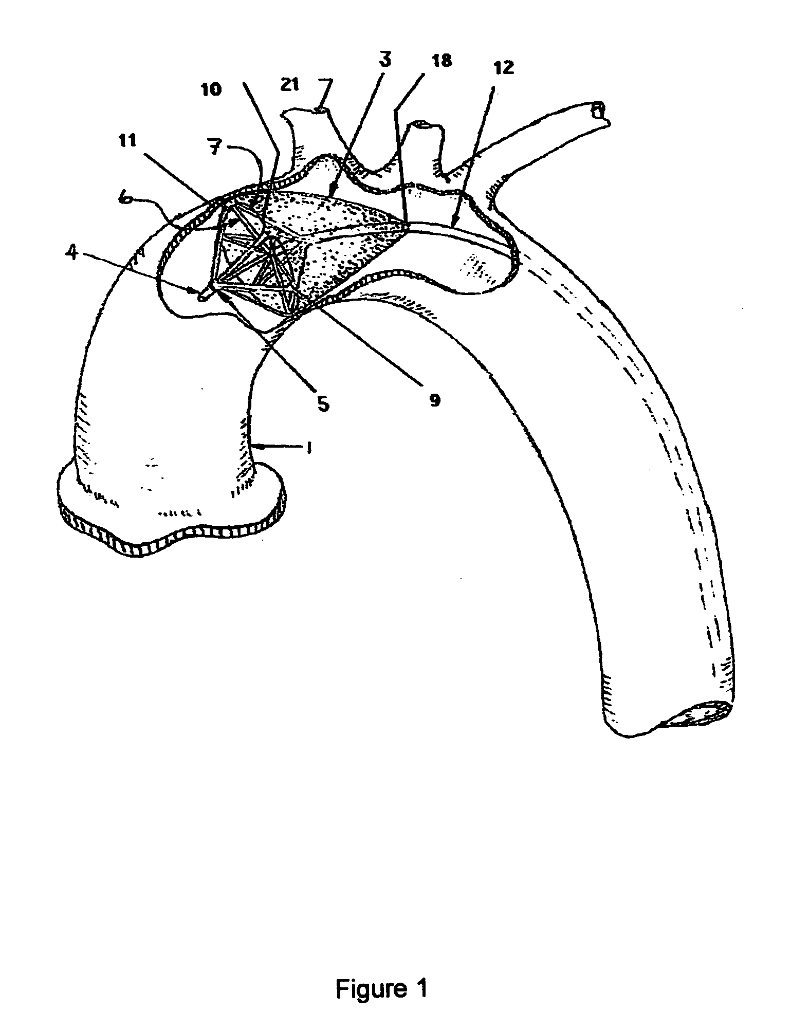
[0040]Several embodiments of the invention are described, with reference to the figures. A first embodiment is shown in FIG. 1, showing a filter deployed within an aorta 1. The catheter system includes three concentric flexible elongated members 12, 13, and 14 having a distal region adapted to enter an artery, and a proximal region extending through the vasculature and eventually outside the body. The catheter system includes a filtration membrane 3, which is lightly stippled in the illustration. The filter has an expansion means, typically comprising several pairs of compression 6 and tension 7 struts disposed about the distal region of the flexible elongated member 12. The system as illustrated has four strut pairs, and might have as few as three, but preferably has six or more preferably eight pairs, to obtain good approximation of the edges of the filter 3 to the wall of the artery 1. When deployed, the distal regions of the struts 6 and 7 are deflected outward from the distal p...

second embodiment

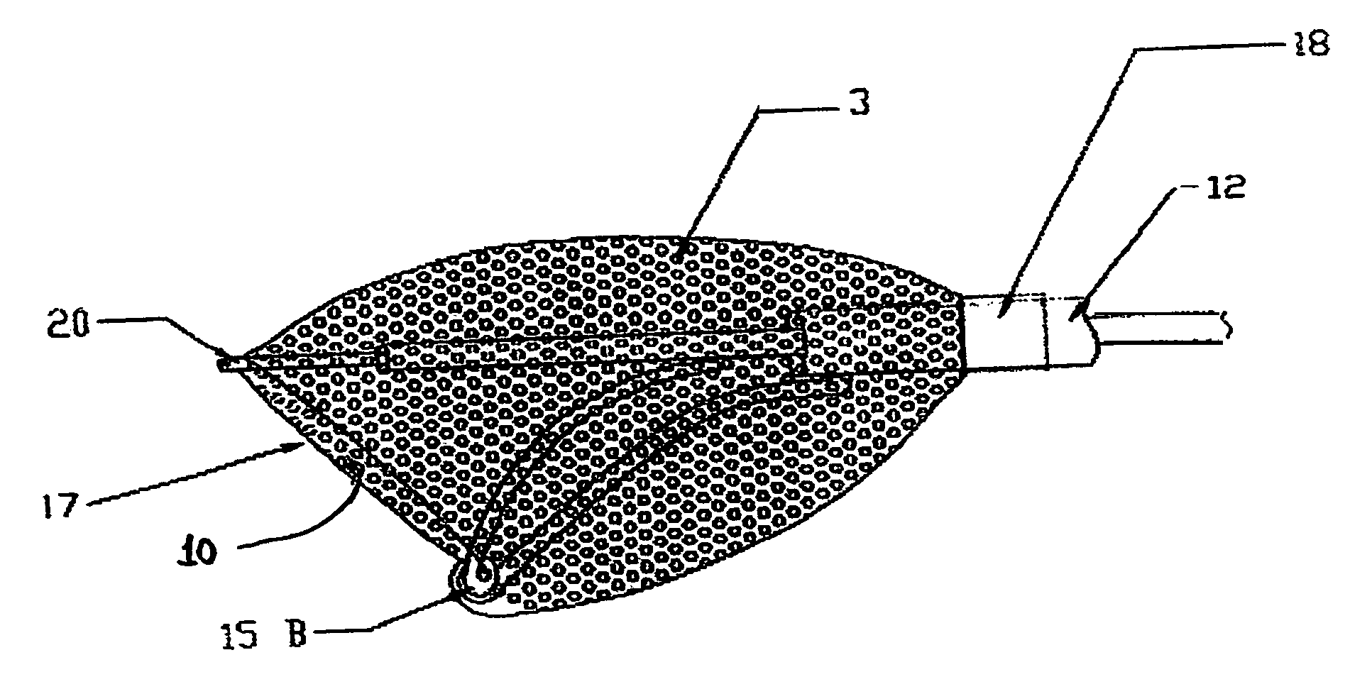
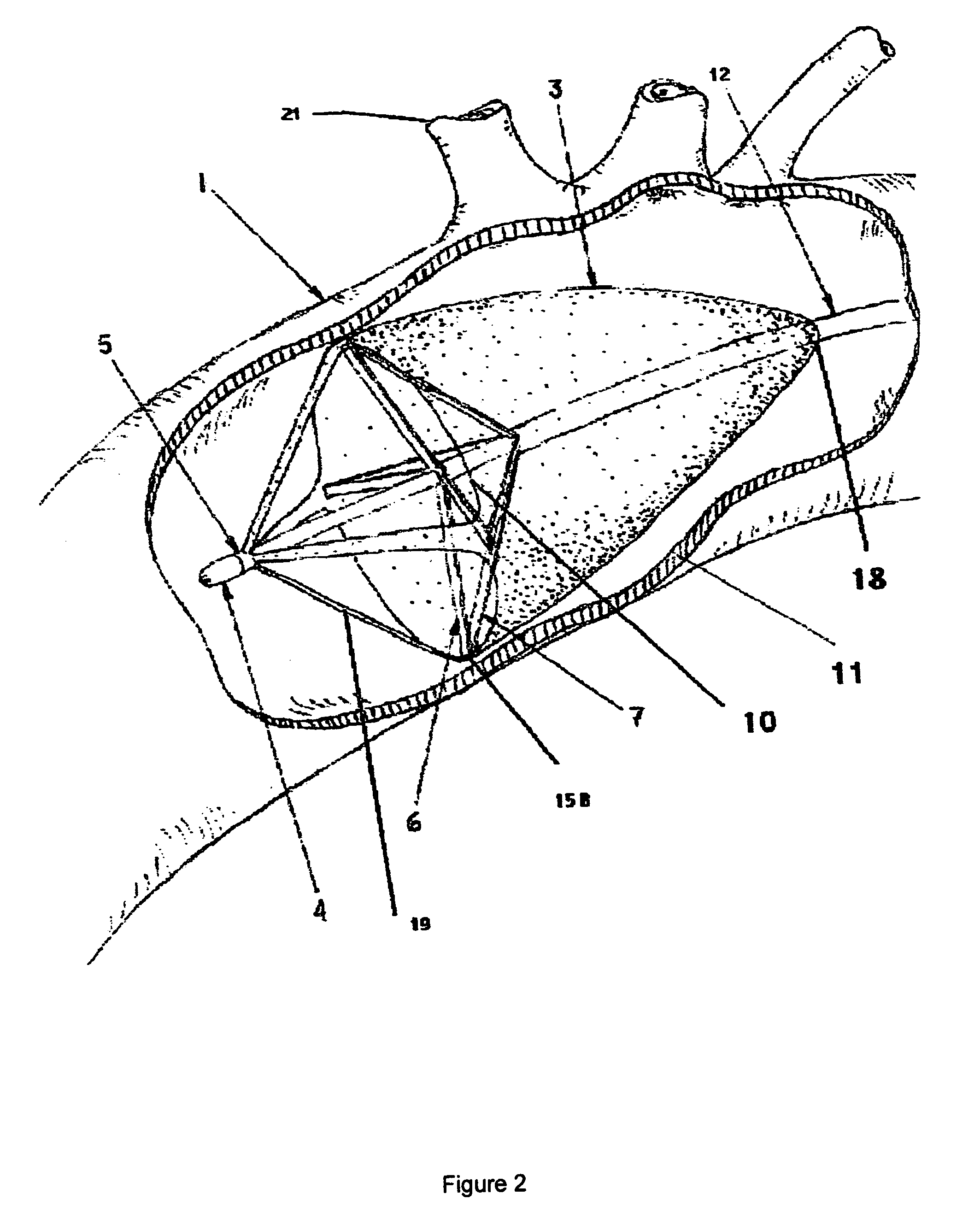
[0051]Another embodiment of this invention is depicted in FIGS. 4 and 5. FIG. 4, similar to FIG. 1, shows a device of the second embodiment deployed at an appropriate location in the aorta. Key labeled parts, numbered as in previous figures, are three tubes 12, 13 and 14; tension and compression struts 7 and 6; a membrane 3, shaded; and a new component, a flexible hoop 17, to which the open proximal end of the filter membrane 3 is attached. It can be seen that the filter 3 is asymmetrically disposed with respect to the catheter tubes. Also labeled is the innominate artery 21 (also called the brachiocephalic trunk), which is the closest to the heart of the arterial branches from the aorta. Positioning the filter “upstream” of this artery, as illustrated here, will provide maximal protection from infarctions caused by debris such as clots and plaque. Entry of the catheter into the circulation through the femoral artery is schematically illustrated at lower left.

[0052]The operation of ...


PUM


Abstract

An improved arterial catheter device for capturing emboli within the aorta and other arteries is described. The system typically includes an elongated catheter member bearing a filtration apparatus disposed at its the distal region, comprising a filter membrane and a mechanism for deploying and collapsing the filter. For reliable deployment, the deployment mechanism comprises at least one pair of struts, one being a compression strut and the other a tension strut. In use, the catheter is positioned so that the filter membrane is down stream from the possible embolic source and upstream from any vital organs of concern. When deployed the filter membrane will capture emboli from the blood stream, and upon filter removal will extract the emboli from the patient.

Description

CROSS REFERENCE TO RELATED APPLICATIONS[0001]This application claims the benefit of the priority of U.S. Ser. No. 60 / 407,624 filed Sep. 3, 2002, and of U.S. Ser. No. 60 / 453,244, filed Sep. 11, 2003.[0002]1. Field of the Invention[0003]This invention relates to improved methods and apparatus for capturing emboli within a blood vessel such as the aorta. More particular, it relates to a catheter with a mechanically deployable filter for capturing emboli dislodged during bypass surgery, thereby protecting the patient from the associated adverse effects. The device is characterized by using paired compression and tension struts for filter deployment. The struts are controllable from a proximal handle of the device.[0004]2. Background of the Invention[0005]Over recent decades tremendous advances have been made in the area of heart surgery, including such life saving surgical procedures as coronary artery bypass grafting (CABG) and cardiac valve repair or replacement. Cardiopulmonary bypas...

Claims


Application Information

Patent Timeline
IPC IPC(8): A61M29/00A61F
CPCA61F2/013A61F2230/008A61F2230/0021A61F2230/0006A61F2002/018
Inventor MORRILL, RICHARD JFAGAN, JOHN R.WILLIAMS, DAVID O.
Owner ADVANCED VASULAR TECH
Why Eureka
Try Eureka