
On-line rapid automatic frequency calibration circuit for frequency synthesizer and method thereof

An automatic frequency calibration and frequency synthesizer technology, applied in the electronic field, can solve the problems of difficult to meet the requirements of some communication standards, long calibration time of the frequency synthesizer, and increased circuit complexity, etc., to achieve simple and reliable implementation, avoid counting Long-lasting effect to avoid adverse effects

Active Publication Date: 2011-10-19
GUANGZHOU RUNXIN INFORMATION TECH
View PDF4 Cites 17 Cited by
  • Summary
  • Abstract
  • Description
  • Claims
  • Application Information

AI Technical Summary

Problems solved by technology

[0010] With the continuous development of technology, people have higher and higher requirements for wireless communication. For example, it is required that the same transceiver can meet different communication standards and cover multiple frequency bands. Wide frequency band not only increases the complexity of the circuit, but also makes it more difficult to improve the noise. It also makes the calibration time of the frequency synthesizer longer, which is difficult to meet the requirements of some communication standards using traditional automatic frequency calibration techniques

Method used


Image

  • On-line rapid automatic frequency calibration circuit for frequency synthesizer and method thereof
  • On-line rapid automatic frequency calibration circuit for frequency synthesizer and method thereof
  • On-line rapid automatic frequency calibration circuit for frequency synthesizer and method thereof

Examples


Embodiment Construction

[0026] The specific implementation manners of the present invention will be further described in detail below in conjunction with the accompanying drawings.

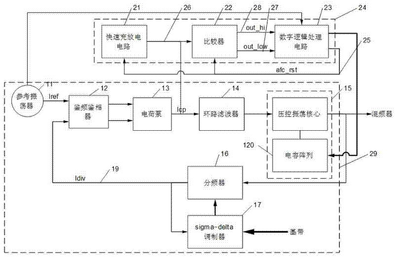
[0027] Such as figure 2 The frame diagram of the frequency synthesizer adopting the automatic frequency calibration circuit of the present invention is shown. The structure of the frequency synthesizer is the prior art, and will not be described in detail. The online fast automatic frequency calibration circuit of the frequency synthesizer of the present invention mainly includes a fast charging and discharging circuit 21, a comparator circuit 22 and a digital logic processing circuit 23;

[0028] The described fast charging and discharging circuit 21 has a control terminal 25 and a charging and discharging output terminal 26, and the charging and discharging output terminal 26 is connected to a loop filter. The voltage on the discharge output terminal 26 has no effect; when the signal of the control terminal 25 is hig...


PUM


Abstract

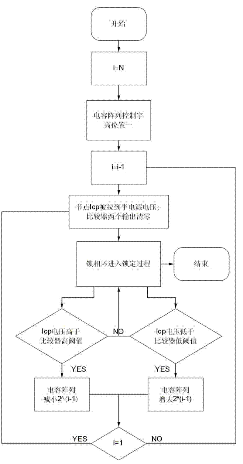
The invention discloses an on-line rapid automatic frequency calibration circuit for frequency synthesizer and a method thereof. The automatic frequency calibration circuit mainly comprises a rapid charge and discharge circuit (21), a comparator circuit (22) and a digital logic processing circuit. The calibration method in the invention adopts closed loop calibration. The main thinking is taking capacitance array as expansion of variable capacitance and imitating establishment process of phase-locked loop only with variable capacitance and without capacitance array to integrate automatic frequency calibration process and the phase-locked loop establishment process as one body. According to the invention, calibration time of frequency synthesizer is reduced, thus output frequency of the frequency synthesizer can be switched rapidly.

Description

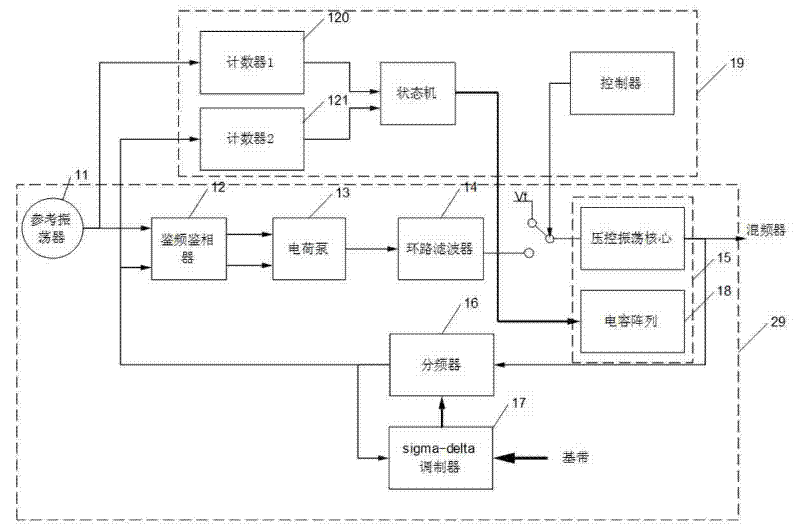
technical field [0001] The invention belongs to the field of electronic technology, and is specifically applicable but not limited to a fast frequency calibration method and circuit of a frequency synthesizer in a radio frequency transceiver. Background technique [0002] At present, in wireless transceivers, frequency synthesizers are used to generate programmable and precise oscillation signals, such as figure 1 As shown, it generally consists of a reference oscillator 11, a frequency and phase detector 12, a charge pump 13, a loop filter 14, a voltage-controlled oscillator 15 and a frequency divider 16. A frequency synthesizer capable of generating fractional frequency division ratios typically also includes a sigma-delta modulator 17 . The output frequency range of the frequency synthesizer 29 depends on the output frequency range of the voltage-controlled oscillator 15. In order to obtain lower phase noise, the voltage-controlled oscillator is generally realized by an ...

Claims


Application Information

Patent Timeline
Patent Type & Authority Applications(China)
IPC IPC(8): H03L7/08H03L7/099
Inventor 李正平王明照
Owner GUANGZHOU RUNXIN INFORMATION TECH
Learn More