Optical apparatus using vertical light receiving element

a technology of optical apparatus and light receiving element, which is applied in the field of optical apparatus, can solve the problems of more working errors and problematic prior art techniques

Active Publication Date: 2005-07-26
SAMSUNG ELECTRONICS CO LTD
View PDF3 Cites 20 Cited by
  • Summary
  • Abstract
  • Description
  • Claims
  • Application Information

AI Technical Summary

Benefits of technology

[0012]Accordingly, the present invention has been made to overcome the above-mentioned problems and provides additional advantages, by providing an optical apparatus having a vertical light receiving element which can two-dimensionally couple a light signal generated from a light source.

Problems solved by technology

However, in the conventional structure, which employs the three-dimensional optical coupling method using a vertical light receiving element, it is necessary to adjust the vertical position of the photo device—in the case of the single mode, and further position adjusting, assembling, and fixing operations must be performed within the error range of ±1 μm.
Therefore, the prior art technique is problematic, in that more working errors may happen during the optical coupling process in comparison with the two-dimensional package having two degrees of freedom.

Method used


Image

  • Optical apparatus using vertical light receiving element
  • Optical apparatus using vertical light receiving element
  • Optical apparatus using vertical light receiving element

Examples


Embodiment Construction

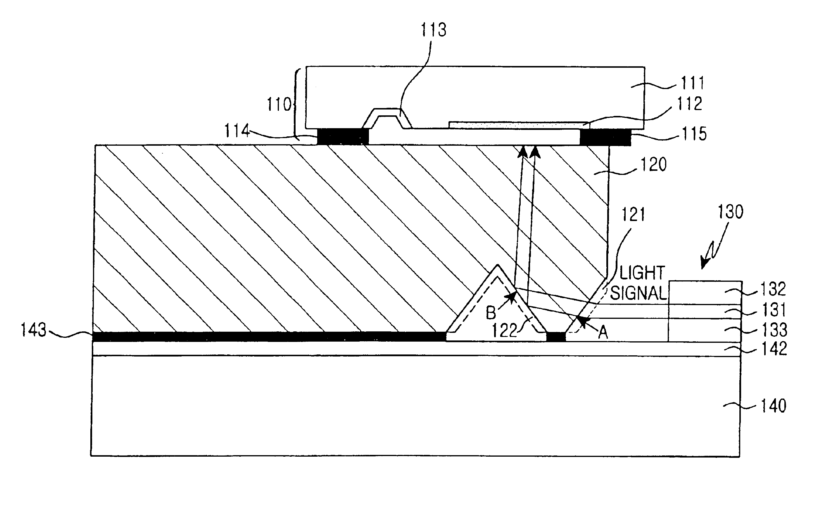
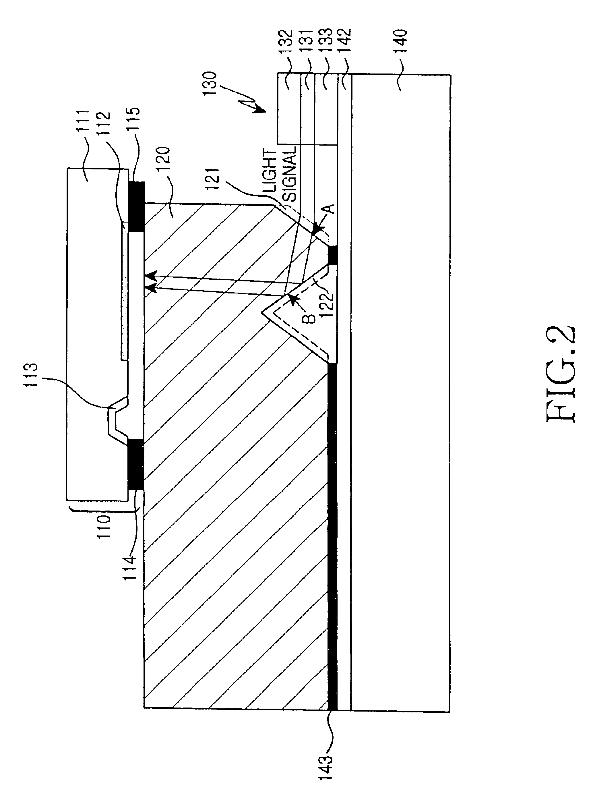
[0023]Hereinafter, an optical apparatus using a vertical light receiving element according to preferred embodiments of the present invention will be described with reference to the accompanying drawings. It is to be noted that the same elements are indicated with the same reference numerals throughout the drawings. For the purposes of clarity and simplicity, a detailed description of known functions and configurations incorporated herein will be omitted as it may make the subject matter of the present invention unclear.

[0024]Referring to FIG. 2, a light receiving element according to the embodiment of the present invention includes a vertical photo detector 110 having a photo-absorption layer and an optical bench 120 on which the photo detector 110 is disposed thereon. In the optical bench 120, a first groove A is formed with a predetermined slant angle at the edge of the surface that is opposite to the upper surface on which the photo detector 110 is disposed, and a second groove B...


PUM


Abstract

An optical apparatus having a vertical light receiving element is disclosed. The optical apparatus is configured to couple light generated from a light source using the vertical light receiving element, then transforms the received light signals into an electric signal. The optical apparatus includes: a vertical photo detector having a photo-absorption layer; and an optical bench on which the photo detector is disposed. The optical bench having a first groove and a second groove formed adjacent to each other, the first groove having a predetermined inclination and being formed at an edge of a first surface of the optical bench, and the first surface being opposite to a second surface of the optical bench, on which the photo detector is disposed, such that a light signal incident to the first groove is refracted at a predetermined angle by the first groove; and the light signal, which has been refracted by the first groove, is totally reflected by the second groove. As a result, that the light signal is substantially and vertically incident into the photo-absorption layer.

Description

CLAIM OF PRIORITY[0001]This application claims priority to an application entitled “Optical apparatus using vertical light receiving element,” filed in the Korean Intellectual Property Office on Mar. 28, 2003 and assigned Serial No. 2003-19620, the contents of which are hereby incorporated by reference.BACKGROUND OF THE INVENTION[0002]1. Field of the Invention[0003]The present invention relates to an optical apparatus, and more particularly to an optical apparatus using a vertical light receiving element for coupling a light signal from a light source and then transforming the received light signal into an electric signal.[0004]2. Description of the Related Art[0005]In order to manufacture a light module of ultra-low cost, the light module must be manufactured in complete automatization, that is, in a chip mounting method. Two-dimensional optical coupling is necessary in optical coupling, such as optical coupling between a laser diode and a photodiode, between a fiber and a photodio...

Claims


Application Information

Patent Timeline
Patent Type & Authority Patents(United States)
IPC IPC(8): H01L31/0232G02B6/42H01S5/023
CPCG02B6/4214H01S5/02236H01S5/02248H01S5/0683H01S5/023H01S5/0233H01S5/0235H01S5/02325G02B6/42
Inventor YANG, SEUNG-KEEJEON, BYUNG-OKKANG, HWA-YOUNGRHEE, DO-YOUNG
Owner SAMSUNG ELECTRONICS CO LTD
Why Eureka
Try Eureka