
Methods and apparatus for treatment of mitral valve insufficiency

a technology for mitral valves and apparatuses, applied in the field of mitral valve insufficiency treatment, can solve the problems of aggravated difficulties, low pumping efficiency of the heart, and high risk of complications for patients, and achieves a simple and reliable way of positioning

Active Publication Date: 2010-07-15
RECOR MEDICAL INC
View PDF106 Cites 85 Cited by
  • Summary
  • Abstract
  • Description
  • Claims
  • Application Information

AI Technical Summary

Benefits of technology

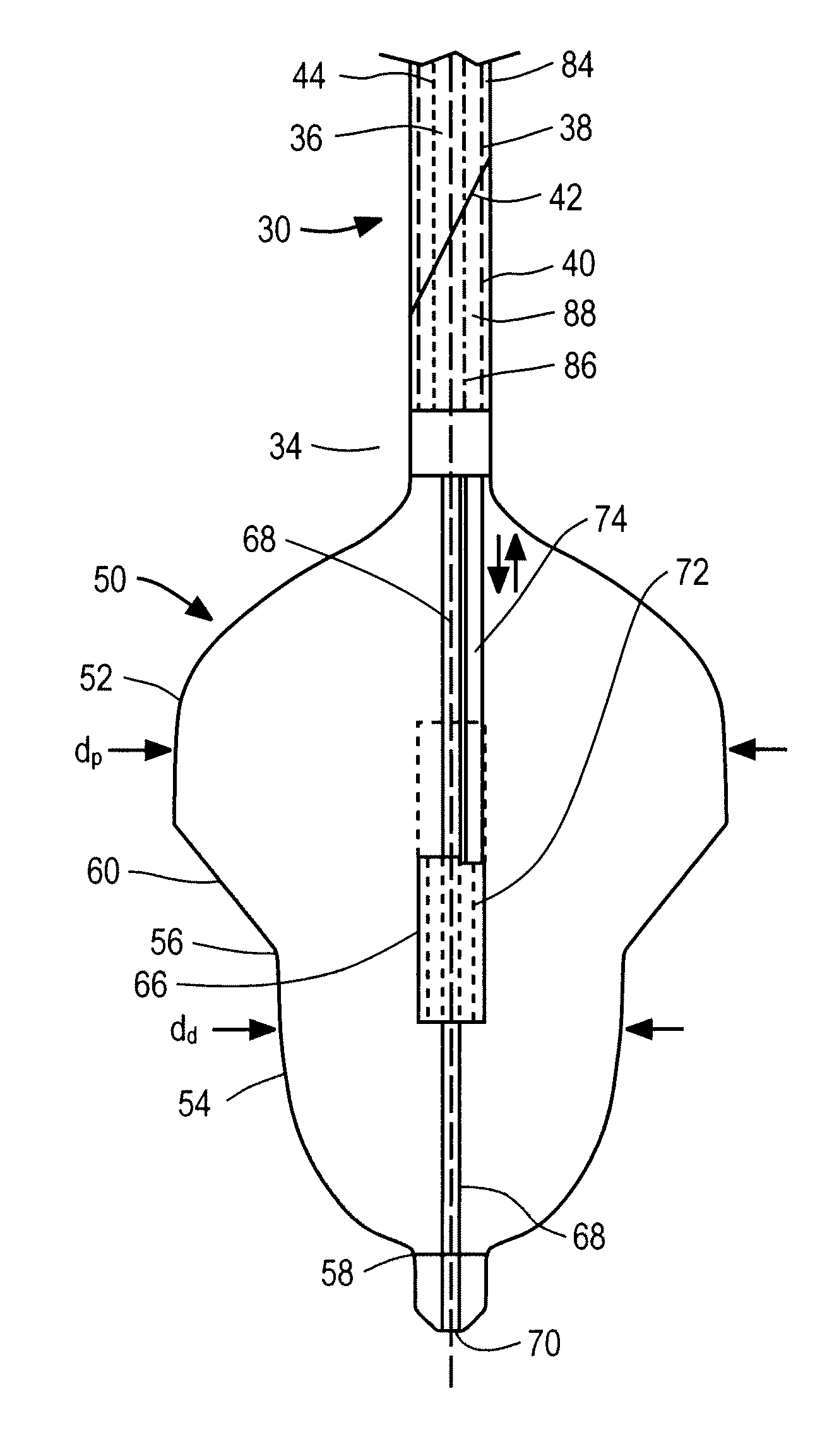
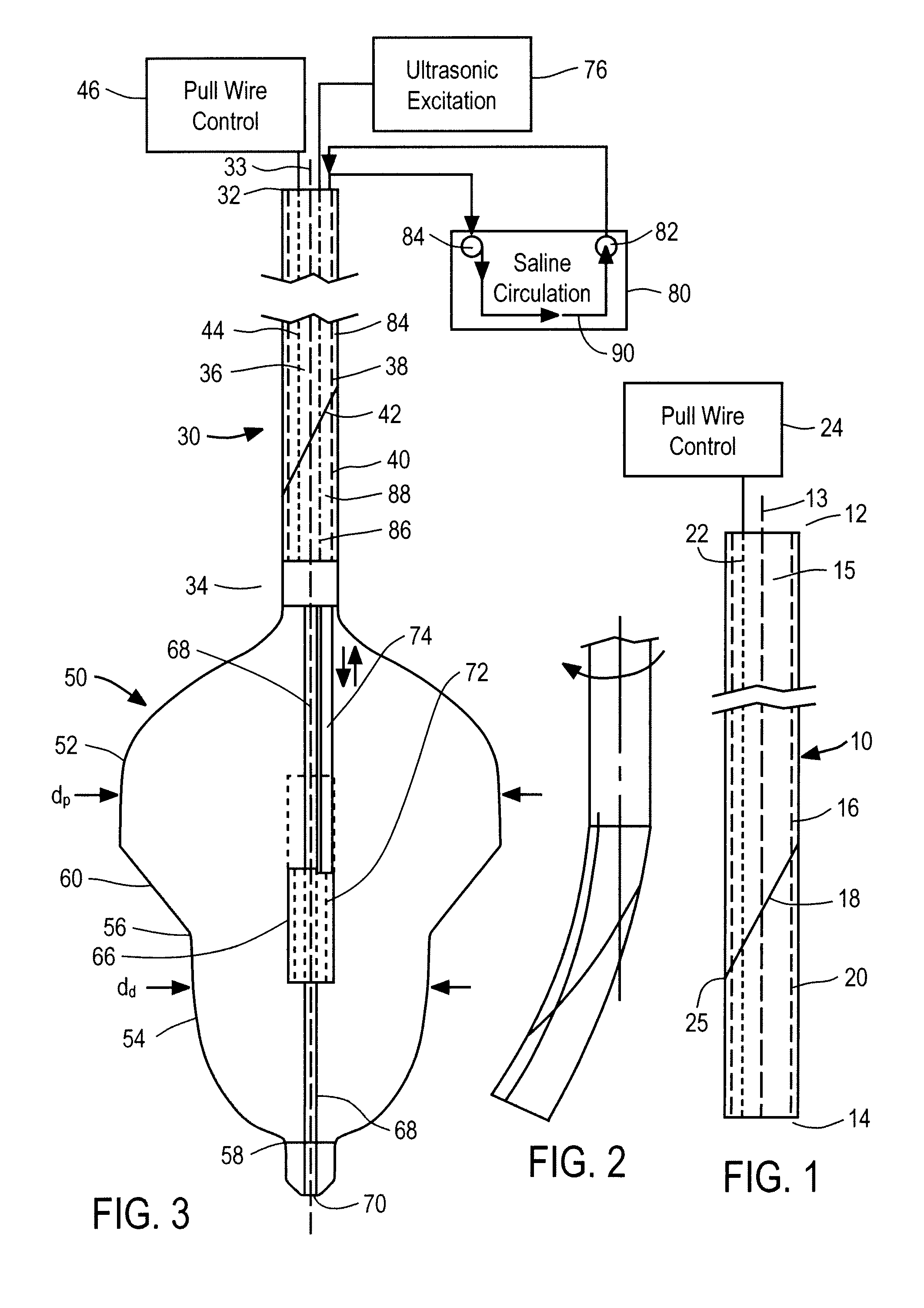
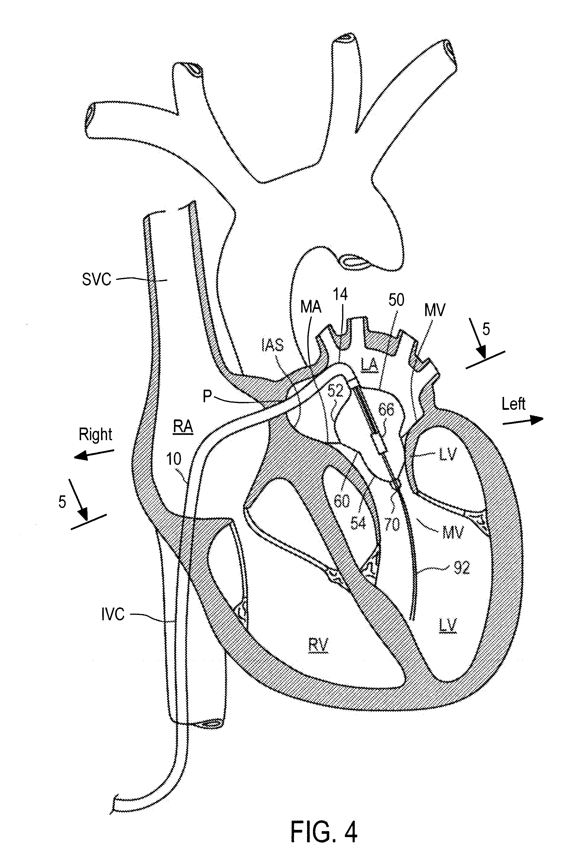
[0010]As further discussed below, the expansible structure may be brought into engagement with the left posterior aspect of the mitral annulus so that the ultrasonic transducer is disposed within the annulus, closer to the posterior aspect than to the anterior aspect of the mitral annulus, and closer to the right aspect of the mitral annulus than to the left aspect, but nonetheless spaced apart from the posterior and left aspects. The transducer may be actuated so as to emit ultrasonic waves. The ultrasonic waves tend to heat the posterior and left aspects of the mitral annulus preferentially. As further discussed below, heating of the posterior aspect is particularly desirable, in that the posterior aspect is rich in collagen and tends to shrink readily with heating.
[0013]As further discussed below, the steerable sheath desirably in combination with the guidewire provides a relatively simple and reliable way of positioning the emitter unit, which allows the emitter unit to remain in place in the beating heart long enough to perform the procedure.

Problems solved by technology

This diminishes the pumping efficiency of the heart.
This procedure requires open heart surgery with long recuperation time, and exposes the patient to high risk of complications.
Many of the individuals who need mitral valve repair are elderly, which tends to aggravate the difficulties associated with open heart surgery.
Annuloplasty as commonly practiced requires a major thoracic surgery with substantial recuperation time and risk of complications.
It is difficult to provide such accurate positioning of a transducer within a beating heart.
Although it is possible to momentarily halt the heartbeat, perform the procedure and then restart the heart, this adds considerable risk to the procedure.
Moreover, localized heating of the annulus by a transducer in contact with the annulus introduces the further risk of damage to the epithelial cells overlying the annulus with attendant risk of thrombus formation after surgery.

Method used


Image

  • Methods and apparatus for treatment of mitral valve insufficiency
  • Methods and apparatus for treatment of mitral valve insufficiency
  • Methods and apparatus for treatment of mitral valve insufficiency

Examples


example 1

[0053]Four dogs are treated using apparatus and techniques substantially as described above with reference to FIGS. 1-5. The dimensions of the mitral annulus are measured in vivo by imaging techniques pretreatment, immediately post-treatment and at one, two, three, and four weeks post-treatment. The results are as indicated in FIGS. 6 and 7, and demonstrate substantial shrinkage of the mitral annulus. The dogs did not evidence adverse effects from the procedure. Their circulation and cardiac rhythm remained intact after the procedure. Upon dissection, the heart did not exhibit scarring of the epithelial lining.

[0054]Referring now to FIG. 8, apparatus according to a further embodiment of the invention is described, and incorporates balloon 150 and transducer 166 mounted on distal end 134 of a catheter. In this embodiment, however, balloon 150, in the inflated condition as depicted, has narrow section 100 surrounding transducer 166 and distal region 102 distal to the narrow section, t...


PUM


Abstract

Mitral valve insufficiency is treated by introducing an expansible device such as a balloon bearing a an ultrasonic transducer into the heart so that the transducer is positioned adjacent the mitral annulus but spaced from the mitral annulus, and actuating the transducer to heat the mitral annulus, denature collagen in the annulus and thereby shrink the annulus.

Description

I. CROSS-REFERENCE TO RELATED APPLICATIONS[0001]This application claims the benefit of U.S. Provisional Patent Application No. 61 / 204,744, filed Jan. 9, 2009 and entitled “Treatment of Mitral Valve Insufficiency,” the entire contents of which are incorporated by reference herein.I. BACKGROUND OF THE INVENTION[0002]The present invention relates to treatment of cardiac valves in a mammalian subject.[0003]Humans and other mammals have a four-chambered heart. Blood from the body flows into the right atrium, and from the right atrium through the tricuspid valve to right ventricle. The right ventricle pumps the blood through the pulmonary arteries to the lungs. Blood from the lungs returns through the pulmonary veins to the left atrium, and flows from the left atrium through the mitral valve, into the left ventricle. The left ventricle, in turn, pumps the blood through the body. As the heart beats, the atria contract to pump the blood into the ventricles, and then the ventricles contract,...

Claims


Application Information

Patent Timeline
Patent Type & Authority Applications(United States)
IPC IPC(8): A61N7/00A61M29/00
CPCA61B2017/00106A61B2017/00703A61B2017/22051A61N2007/0078A61B2019/5276A61N7/022A61B2018/00023A61B2090/378
Inventor WARNKING, REINHARDJUNG, EUGENE J.ZOU, YONGSEGUIN, JACQUESIYER, MANO
Owner RECOR MEDICAL INC
Learn More