Power transmission system

a power transmission system and power technology, applied in the direction of electric power, transportation and packaging, electric vehicles, etc., can solve the problems of failure to disclose the size of the reference potential electrode, the reference potential of the power receiving device cannot be stabilized, and the malfunction etc., to achieve the effect of stabilizing the reference potential of the power receiving devi

Active Publication Date: 2018-05-15
MURATA MFG CO LTD
View PDF20 Cites 0 Cited by
  • Summary
  • Abstract
  • Description
  • Claims
  • Application Information

AI Technical Summary

Benefits of technology

[0040]According to the present invention, the reference potential at the power receiving device side can be made close to the reference potential at the power transmitting device side, thereby stabilizing the reference potential of the power receiving device.

Problems solved by technology

However, the power transmission system as disclosed in International Publication No. 2013 / 054800 pamphlet does not disclose conditions related to the reference potential electrodes, such as their size.
The reference potential of the power receiving device cannot be stabilized in some cases only by providing the reference potential electrodes in the power receiving device and the power transmitting device simply and making them oppose each other.
When the reference potential of the power receiving device is not stable, there is a risk that malfunction occurs in the power receiving device.

Method used


Image

  • Power transmission system
  • Power transmission system
  • Power transmission system

Examples


first embodiment

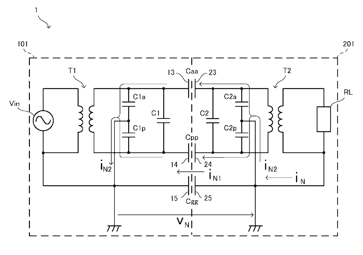
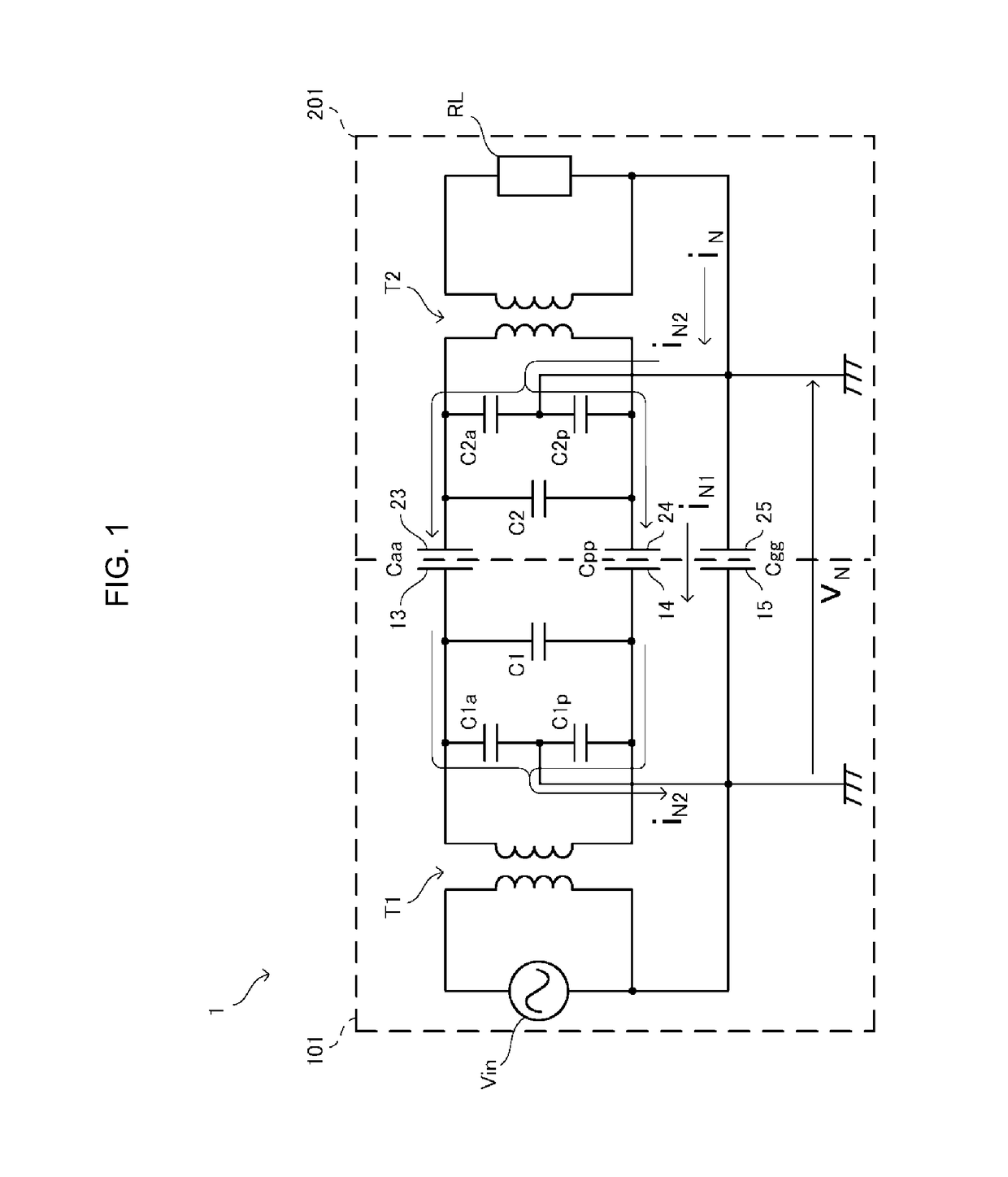
[0053]FIG. 1 is a diagram illustrating a circuit of a power transmission system 1 according to a first embodiment. The power transmission system 1 in the present embodiment is configured by a power transmitting device 101 and a power receiving device 201. The power receiving device 201 is placed on the power transmitting device 101. The power transmitting device 101 transmits electric power to the power receiving device 201 placed thereon (i.e., placed in operative engagement wherein power can be transmitted from the power transmitting device 101 to the power receiving device 201).

[0054]The power receiving device 201 includes a load circuit RL. The load circuit RL can be a secondary battery, a charging circuit, and the like. The power receiving device 201 is typically a portable electronic device such as a cellular phone, a personal digital assistant (PDA), a portable music player, a notebook-type personal computer (PC), and a digital camera. The power receiving device 201 charges t...

second embodiment

[0106]FIG. 11 is a diagram illustrating a circuit of a power transmission system according to a second embodiment. In the first embodiment, electric power is transmitted to the power receiving device from the power transmitting device by the electric field coupling method. In the present embodiment, electric power is transmitted to the power receiving device from the power transmitting device by magnetic field coupling.

[0107]In this example, in a power transmitting device 102, a transmitting-side coil 16 is connected to the secondary coil of the step-up transformer T1 instead of the active electrode and the passive electrode. Further, in a power receiving device 202, a receiving-side coil 26 is connected to the primary coil of the step-down transformer T2 instead of the active electrode and the passive electrode. It should be noted that other configurations are the same as those in the first embodiment.

[0108]When the power receiving device 202 is placed in operative engagement with ...


PUM


Abstract

In a power transmitting device (101) and a power receiving device (201), active electrodes (13, 23), passive electrodes (14, 24), and reference potential electrodes (15, 25) oppose each other so as to make capacitance coupling, so that capacitances Caa, Cpp, and Cgg are generated. Capacitors having capacitances C1a, C1p, C2a, and C2p are connected to between the reference potential electrode (15) and the active electrode (13), between the reference potential electrode (15) and the passive electrode (14), between the reference potential electrode (25) and the active electrode (23), and between the reference potential electrode (25) and the passive electrode (24), respectively. The power transmission system (1) satisfies any one or more of the conditions of Caa+Cpp<Cgg, C1a+C1p<Cgg, and C2a+C2p<Cgg. With this, the power transmission system stabilizing a reference potential of the power receiving device is provided.

Description

CROSS REFERENCE[0001]The present application is a continuation of International application No. PCT / JP2015 / 051476, filed Jan. 21, 2015, which claims priority to Japanese Patent Application No. 2014-022458, filed Feb. 7, 2014, the entire contents of each of which are incorporated herein by reference.TECHNICAL FIELD[0002]The present invention relates to a power transmission system that transmits electric power to a power receiving device from a power transmitting device wirelessly.BACKGROUND ART[0003]There is a system using an electric field coupling method as a power transmission system. The power transmission system transmits electric power to a power receiving device from a power transmitting device when active electrodes of the power transmitting device and the power receiving device oppose each other and a strong electric field is formed between the two electrodes to establish electric field coupling between the electrodes.[0004]International Publication No. 2013 / 054800 pamphlet ...

Claims


Application Information

Patent Timeline
Patent Type & Authority Patents(United States)
IPC IPC(8): H02J50/05H02J50/12H02J7/02H02J7/34
CPCH02J50/12H02J50/05H02J7/025H02J7/345
Inventor ICHIKAWA, KEIICHI
Owner MURATA MFG CO LTD
Why Eureka
Try Eureka