Pig loader device

a technology for pigs and loaders, which is applied in the direction of pipes/joints/fittings, mechanical devices, pipe elements, etc., can solve the problems of exposing operators to possible pinch points and objects, adhering to and creating obstructions, and dangerous operations, so as to prevent over-retraction/extension of ramrods

Active Publication Date: 2018-06-05
JOHN ANDERSON CONSTR INC
View PDF2 Cites 4 Cited by
  • Summary
  • Abstract
  • Description
  • Claims
  • Application Information

AI Technical Summary

Benefits of technology

[0009]Some embodiments may include a breech shield configured to selectively cover the breech, which may prevent ingress and egress of objects through the breech. Securement means may be used to temporarily secure the breech shield in a covered position. For example, during operation of the device, the breech shield can be secured in the covered position so as to prevent objects from entering and / or exiting the chamber body though the breech.
[0011]The device can enable operators to achieve a preparatory step of pigging a pipeline, which may include loading a pig into the pipeline, in a clean, safe, and efficient manner. When attached to the pipe and with the breech shield in a covered position, the device may generate a contained work area ensuring that moving parts, potential pinch points, and potential projectiles are confined within the device. The device may not only obviate the need for operators to handle the pig when it is being introduced into the pipe, but it can also prevent operators from inadvertently being injured within a pinch point or by an object being projected from within the chamber body.

Problems solved by technology

These compounds, as well as the organic and volatile compounds extracted with the oil and gas, tend to adhere to and create obstructions within the pipeline.
This can be a dangerous operation due to the pressures involved and the forces used to properly seat the pig within the pipe.
Consequently, this exposes operators to possible pinch points and objects subjected to large forces (i.e., objects becoming projectiles).

Method used


Image

  • Pig loader device
  • Pig loader device
  • Pig loader device

Examples


Embodiment Construction

[0026]The following description is of an embodiment presently contemplated for carrying out the present invention. This description is not to be taken in a limiting sense, but is made merely for the purpose of describing the general principles and features of the present invention. The scope of the present invention should be determined with reference to the claims.

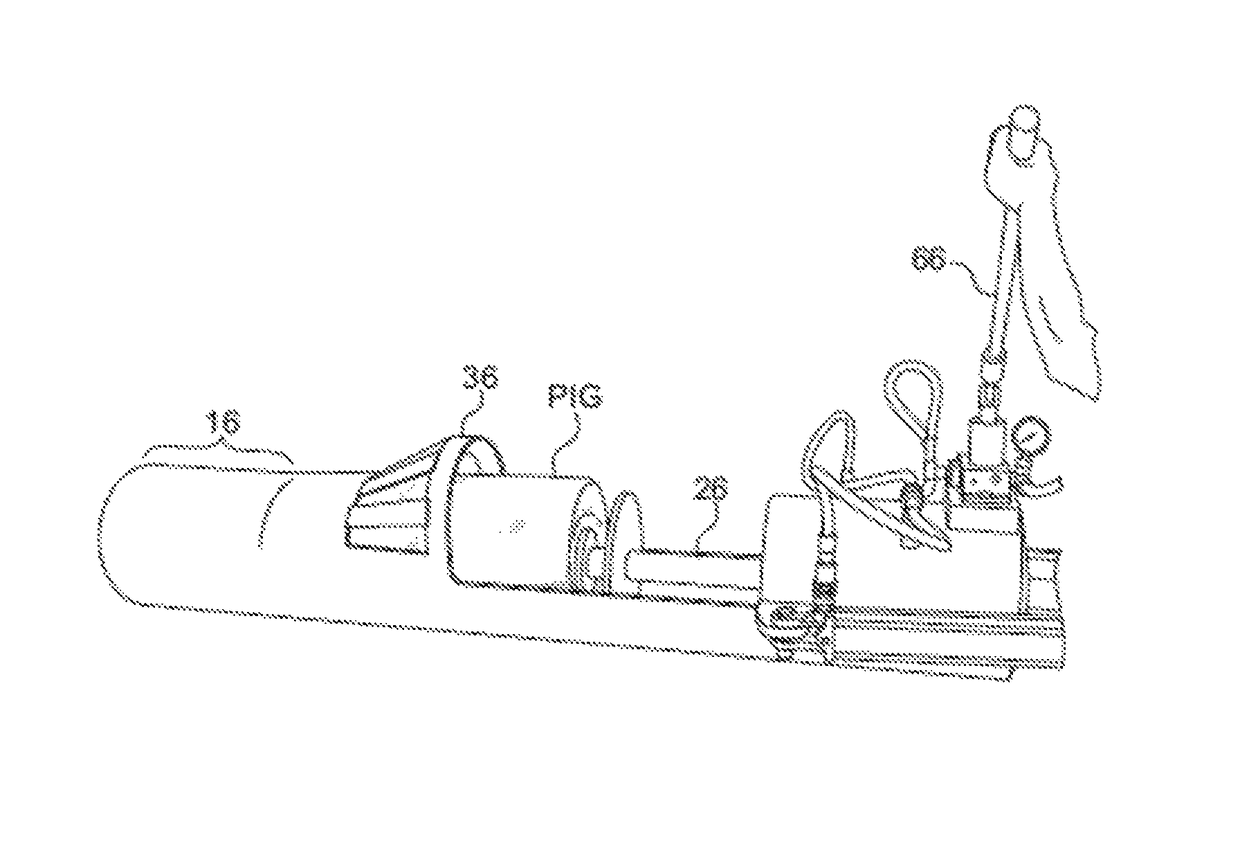
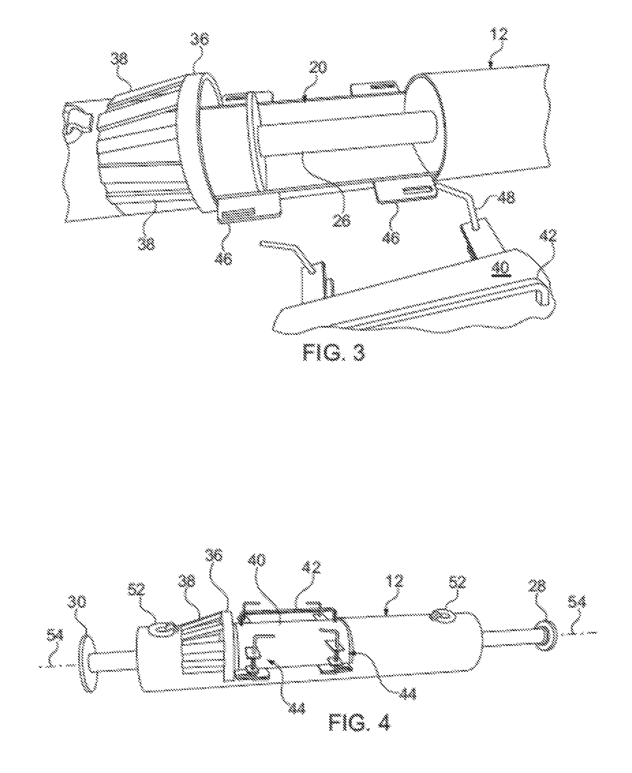
[0027]Referring to FIGS. 1-3, a pig loader device can include a breech assembly 10 having a ramrod compartment 12 at a first distal end 14 and a neck 16 at the second distal end 18, where a chamber body 20 lies between the distal ends 14, 18. The breech assembly 10 may be constructed of a material suitable to withstand strains and stresses associated with repeatedly forcing a pig from the chamber body 20 into an ancillary pipe. The material of construction may include metal or metal alloy. An aperture may be formed into a surface of the chamber body 20 establishing a breech 22 through which a pig (the pig is shown in FIG....


PUM


Abstract

A pig loader device can include a breech assembly having a chamber body, a ramrod compartment, a breech, and a neck. A ramrod having a push plate, a rod, and a breech plate may be disposed within the ramrod compartment and configured to slideably traverse the ramrod compartment and the breech. In use, the device can be connected to an ancillary pipe via the neck, and a pig may be placed within the breech and aligned be to be slid within the breech and neck upon engagement with the ramrod to facilitate pigging operations of a pipeline. The ramrod may then be forced forward to an extended position, thereby urging the pig through the neck to be seated within the pipe. The device may then be detached from the pipe to enable continued pigging operations.

Description

CROSS-REFERENCE TO RELATED APPLICATIONS[0001]This patent application claims the benefit of co-pending U.S. Provisional Patent Application No. 62 / 166,412, filed on May 26, 2015, which is hereby incorporated by reference in its entirety.BACKGROUND OF THE INVENTION[0002]Field of the Invention[0003]Embodiments relate to a device for seating a pig within a pipe, and in particular introducing and properly seating a pig within a pipe through a breech assembly.[0004]Background of the Related Art[0005]Subterranean extraction of oil and gas and transportation of the same typically includes the use of a pipeline to direct the oil and gas under volumetric pressure for processing and tapping. Surfactants, dispersants, and other compounds may be introduced into the pipeline to facilitate the processing of the extracted oil and gas. These compounds, as well as the organic and volatile compounds extracted with the oil and gas, tend to adhere to and create obstructions within the pipeline. A common ...

Claims


Application Information

Patent Timeline
Patent Type & Authority Patents(United States)
IPC IPC(8): F16L55/46
CPCF16L55/46
Inventor ANDERSON, JOHNSHELLEY, JOHN
Owner JOHN ANDERSON CONSTR INC
Why Eureka
Try Eureka