Flashlight and recharging system therefor

a rechargeable and flashlight technology, applied in the manufacture of electric torches/pocket-lamps, secondary cell manufacturing, final product manufacturing, etc., can solve the problems of increased manufacturing costs, and increased manufacturing costs of flashlights

Inactive Publication Date: 2001-03-13
STREAMLIGHT
View PDF50 Cites 67 Cited by
  • Summary
  • Abstract
  • Description
  • Claims
  • Application Information

AI Technical Summary

Problems solved by technology

Machining the mating surfaces of the flashlight after surface finishing increases the cost of fabricating the flashlight due to the expense of a further machining step after anodizing and occasional damage to the finished surface of the flashlight during such further machining.
However, flashlights are often needed when it is dark in the vicinity of the flashlight in the charger unit.
It is recognized that a flashlight that is tightly held within a recharging unit in order to withstand vibration may be difficult to remove from the charging unit.
This latter problem is increased if the flashlight is of compact size.

Method used


Image

  • Flashlight and recharging system therefor
  • Flashlight and recharging system therefor
  • Flashlight and recharging system therefor

Examples


Embodiment Construction

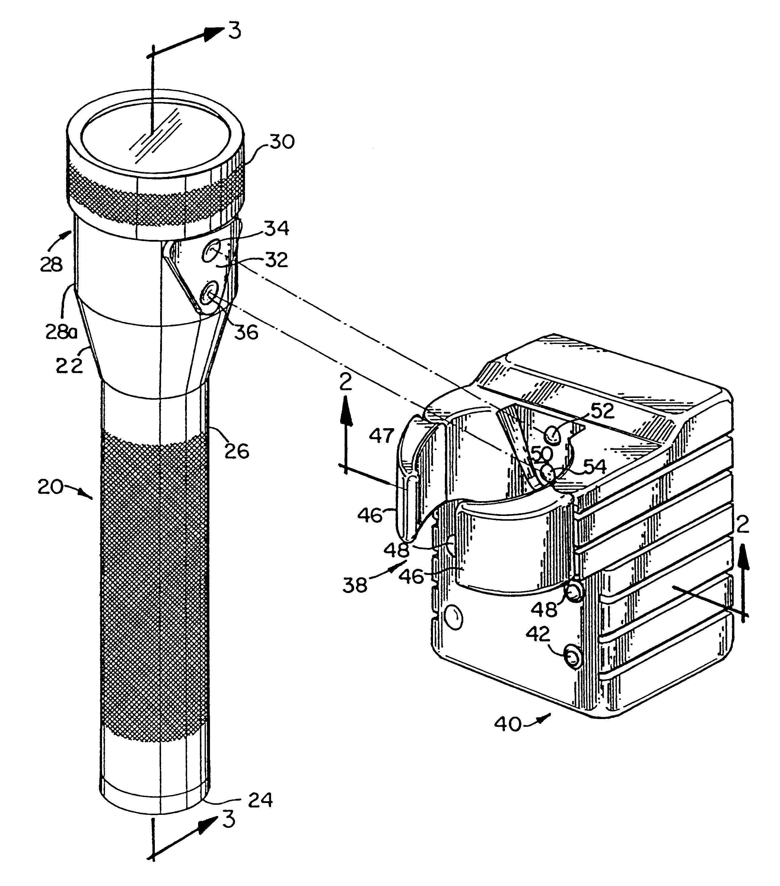
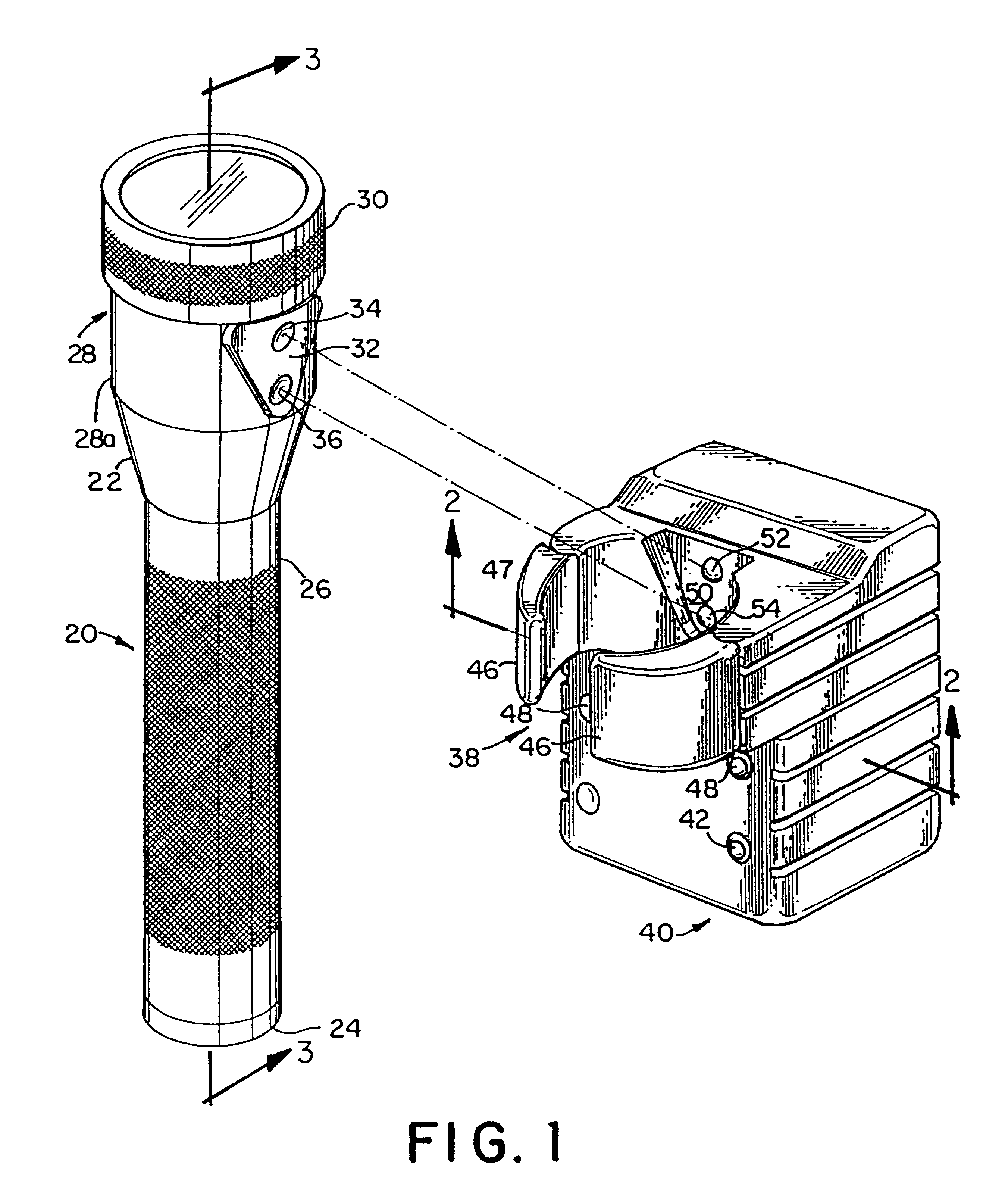
Referring to FIG. 1, there is shown a flashlight 20 and a charging unit 40. The flashlight 20 includes a head assembly 28, a barrel 26, and a tail cap 24. A guide means, such as triangular guide plate 32, is mounted on the side of the head 28. A pair of charging contacts such as concave contacts 34 and 36 are located in the guide plate 32. The guide plate mates with an alignment recess 50 of the charging unit 40, when the flashlight 20 is placed into the charging unit 40. The charging unit 40 includes a pair of jaws 46, a receptacle generally designated 38 which includes the alignment recess 50, and a pair of convex charging terminals 52 and 54 in the alignment recess 50. The recess 50 is shaped to receive and align the guide plate 32, so that the charging terminals 52 and 54 of the charging unit 40 mate with respective charging contacts 34 and 36, when the flashlight is received or mounted in the charging unit 40. The jaws 46 snugly grip the head 28 of the flashlight 20 with a grip...


PUM

PropertyMeasurementUnit
lengthaaaaaaaaaa
electrical energyaaaaaaaaaa
resistanceaaaaaaaaaa

Abstract

A guide plate on the head of the flashlight provides an alignment feature which aligns a pair of flashlight charging contacts with a pair of terminals in charging unit for releasably holding the flashlight in its charging receptacle. The flashlight is held within the charging receptacle in a consistent orientation, so that the flashlight switch may be easily found when the flashlight is grasped. The charging receptacle grips the head portion of the flashlight with a pair of spring-loaded jaws. A battery assembly is provided which presents both positive and negative terminals at the forward end of the battery unit. Connections are made from the forward end of the battery to an interconnection module within the flashlight head assembly.

Description

FIELD OF THE INVENTIONThe present invention relates to a rechargeable flashlight and recharging unit. More specifically, the invention relates to a compact recharging unit having an alignment feature and a rechargeable flashlight which employs a custom battery assembly and a recharging fixture.BACKGROUNDMetal flashlights, such as machined aluminum flashlights, are commonly finished, such as by surface anodization or bright dipping, to protect the surface of the flashlight and to impart an aesthetic quality to the flashlight. The body of such flashlights commonly includes a threaded tail cap for providing access to the battery compartment and which also serves as a battery terminal contact. Since the body of such flashlights usually provides part of the electrical circuit between the batteries and the light bulb, it is necessary for such electrically and physically mating surfaces as the body and the tail cap to be machined subsequent to surface finishing, such as anodizing, so that ...

Claims


Application Information

Patent Timeline
Patent Type & Authority Patents(United States)
IPC IPC(8): F21L4/08F21L4/00H02J7/00H01M2/10H01M2/20H01M10/46H01M10/42H01M6/42B60Q3/00F21V23/00F21V23/04H01M6/44H01M10/04H01M50/50H01M50/548
CPCF21L4/085F21V19/047F21V23/00F21V23/0414H01M6/42H01M6/44H01M10/0422H01M10/46H02J7/0042H02J7/0044H02J7/0045Y10S439/929B60Q3/88Y02E60/10H01M50/213H01M50/50Y02P70/50H01M50/548
Inventor SHARRAH, RAYMOND L.CRAFT, CHARLES W.
Owner STREAMLIGHT
Why Eureka
Try Eureka