In this apparatus, light rays emitted from the image display device are reflected three times in the ocular optical system, thereby enabling the light rays to be folded very effectively and favorably, and thus succeeding in minimizing the thickness of the ocular optical system and realizing reduction in both size and weight of the image display apparatus. Light rays emanating from the observer's
pupil is first reflected toward the observer's face. Then, by the second reflection, the light rays are reflected forwardly from the observer's face side. By the third reflection, the light rays are reflected toward the observer's face again to reach the image display device. Therefore, the image display device lies closer to the observer, and the image display device can be disposed in such a manner that a side thereof which is reverse to its display surface faces the observer. Accordingly, it is possible to realize a head-mounted image display apparatus which projects from the observer's face to an extremely small amount for the same reasons as set forth above with respect to the second image display apparatus according to the present invention. Although it is possible to obtain similar advantageous effects by arranging the ocular optical system such that the fight rays are reflected five or higher odd-numbered times, an increase in the number of reflections causes the distance from the image display device to the observer's
pupil position to lengthen exceedingly. Consequently, it becomes necessary to use longer and larger optical elements. Further, it becomes difficult to ensure a
wide field angle because the
focal length of the ocular optical system becomes long. Accordingly, the use of the ocular optical system which allows the image of the image display device to reach the observer's eyeball by three reflections makes it possible to realize a well-balanced image display apparatus.
by arranging the ocular optical system such that the fight rays are reflected five or higher odd-numbered times, an increase in the number of reflections causes the distance from the image display device to the observer's
pupil position to lengthen exceedingly. Consequently, it becomes necessary to use longer and larger optical elements. Further, it becomes difficult to ensure a
wide field angle because the
focal length of the ocular optical system becomes long. Accordingly, the use of the ocular optical system which allows the image of the image display device to reach the observer's eyeball by three reflections makes it possible to realize a well-balanced image display apparatus.
Further, a surface of the ocular optical system that is disposed immediately in front of the observer's face is adapted to perform both
refraction and reflection. Therefore, it is possible to reduce the number of surfaces needed to form the ocular optical system and hence possible to improve productivity. In addition, if the angle of internal reflection at the first surface is set so as to be larger than the critical angle, it becomes unnecessary to provide the first surface with a reflective
coating. Therefore, even if the transmitting and reflecting regions on the first surface overlap each other, the image of the image display device reaches the observer's eyeball without any problem. Accordingly, the ocular optical system can be arranged in a
compact form, and the
field angle for observation can be widened.
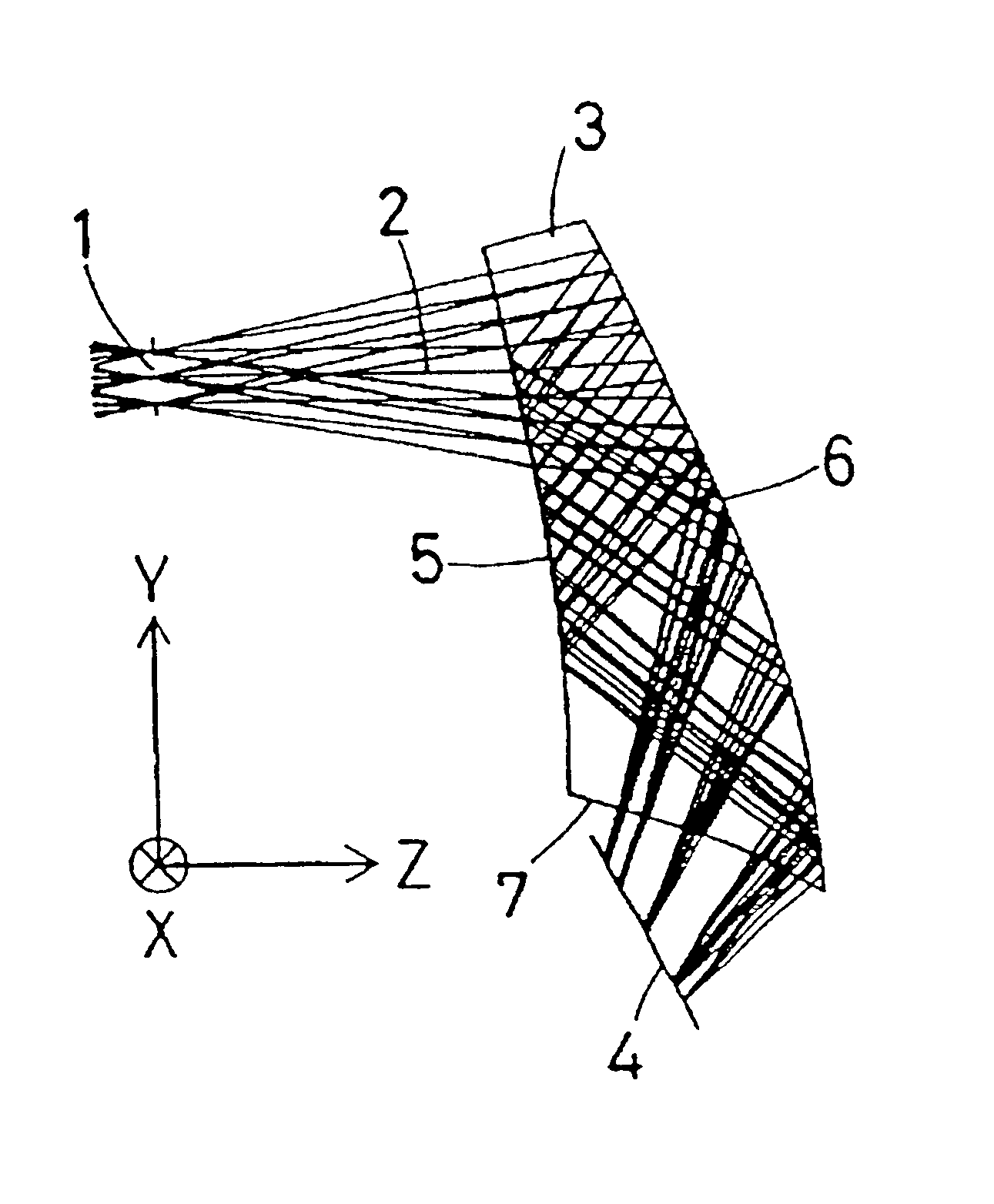
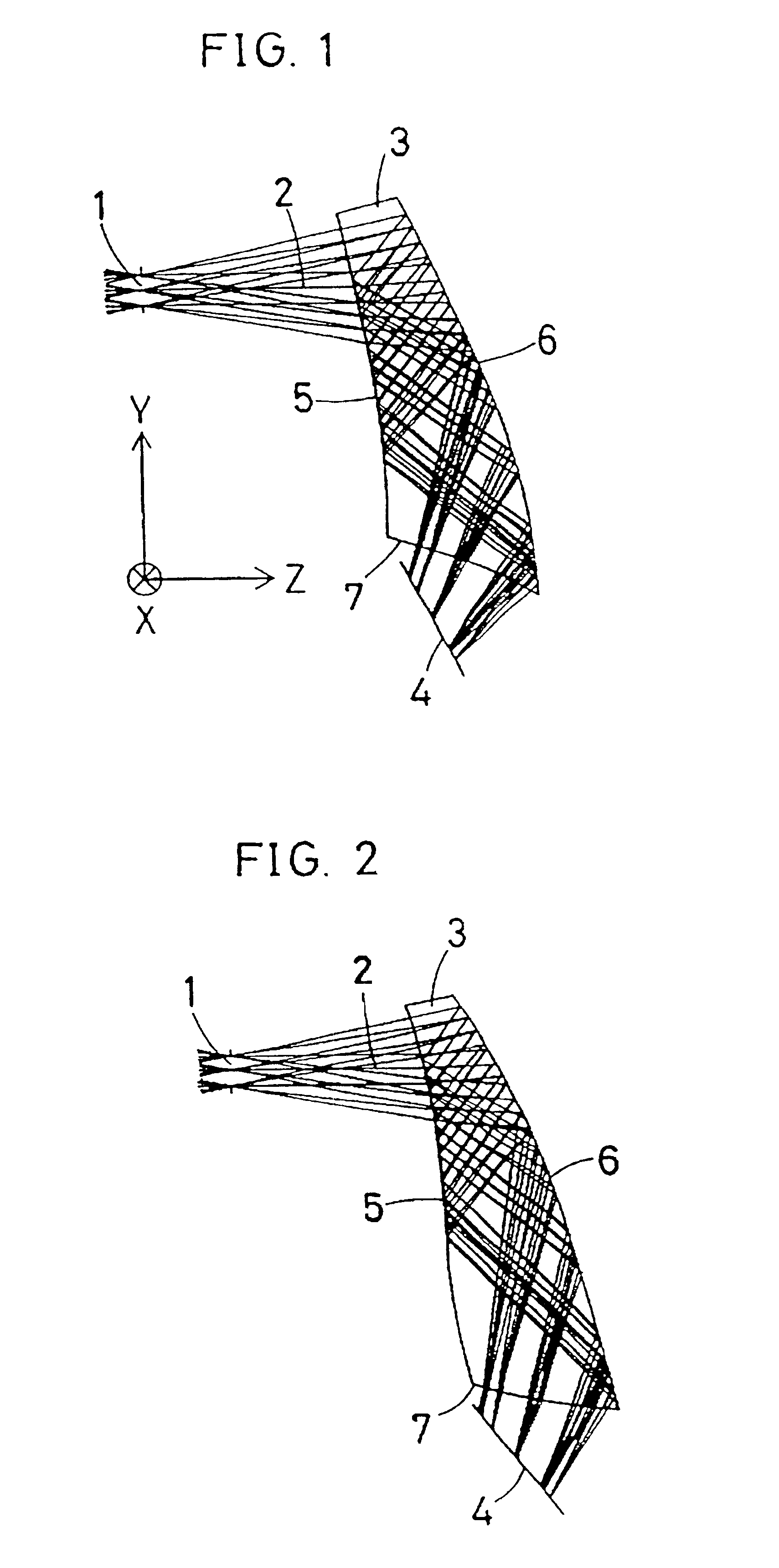
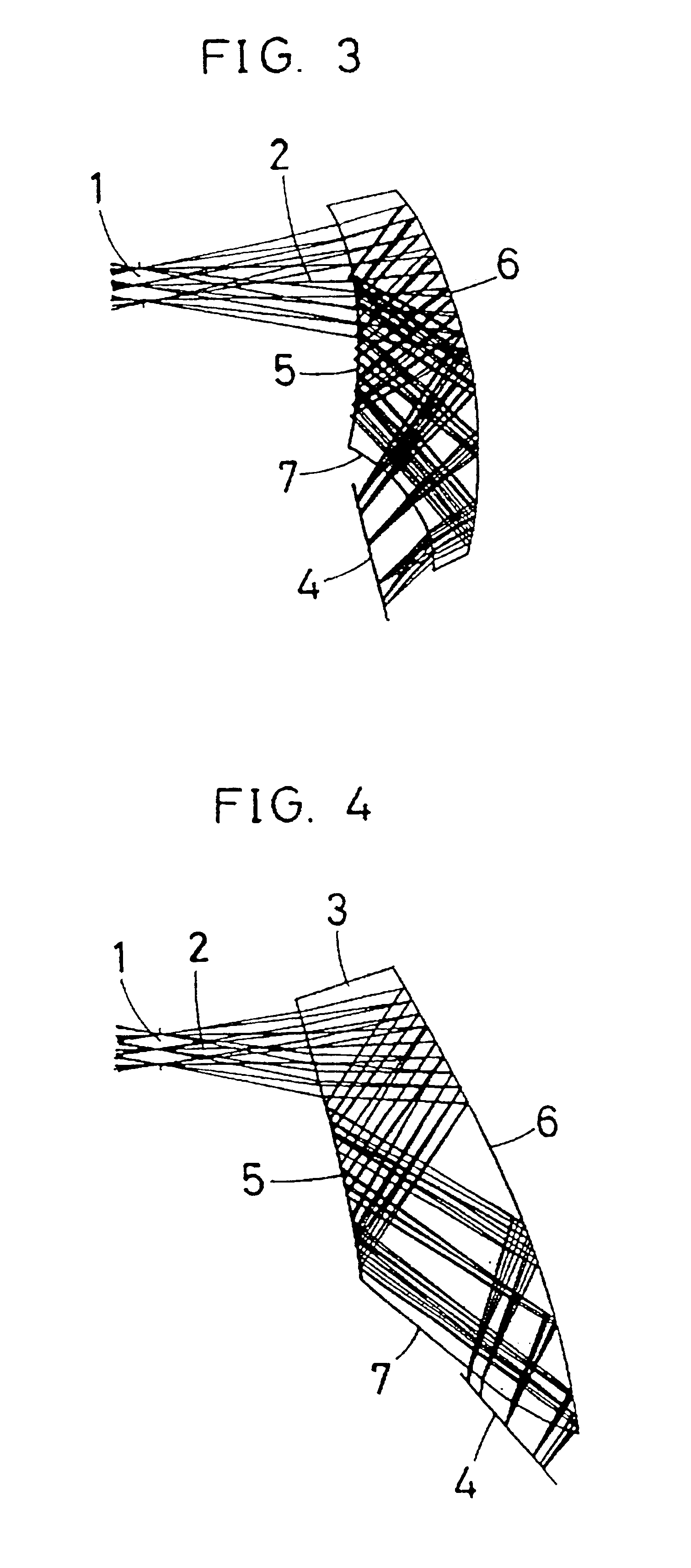
In the third image display apparatus according to the present invention, the ocular optical system has at least three surfaces, and a space formed by the at least three surfaces is filled with a medium having a
refractive index larger than 1. The at least three surfaces include, in the order in which light rays pass in backward
ray tracing from the observer's eyeball to the image display device, a first surface which functions as both a refracting surface and an internally reflecting surface, a second surface which is a reflecting surface facing the first surface and decentered or tilted with respect to an observer's
visual axis, and a third surface which is a refracting surface closest to the image display device, so that reflection takes place three times in the path from the observer's eyeball to the image display device. Examples 1 to 5 (described later) correspond to the arrangement of the third image display apparatus.
In this apparatus, a space that is formed by the first, second and third surfaces of the ocular optical system is filled with a medium having a
refractive index larger than 1, and light rays emitted from the image display device are reflected three times in the ocular optical system, thereby enabling the light rays to be folded very effectively and favorably, and thus succeeding in minimizing the thickness of the ocular optical system realizing reduction in both size and weight of the image display apparatus, and providing the observer with a clear observation image having a wide
exit pupil diameter and a wide
field angle.
By filling the space formed by the first, second and third surfaces with a medium having a refractive index larger than 1, light rays from the pupil are refracted by the first surface, and it is therefore possible to minimize the height at which extra-axial principal and subordinate rays are incident on the second surface. Consequently, the height of the principal
ray at the second surface is low, and therefore, the size of the second surface is minimized. Thus, the ocular optical system can be formed in a compact structure. Alternatively, the field angle can be widened. Further, because the height of the subordinate rays is reduced, it is possible to minimize comatic aberrations produced by the second surface, particularly higher-order comatic aberrations.

