Water-cooled extruder improvements

Inactive Publication Date: 2016-03-31
CHEMAGINEERING
View PDF3 Cites 2 Cited by
  • Summary
  • Abstract
  • Description
  • Claims
  • Application Information

AI Technical Summary

Benefits of technology

[0007]Accordingly, it is an object of the present invention to reduce unscheduled outages and prolong the operating lifetime of water-cooled extrusion equipment by reducing surface and component corrosion of the cooling water-carrying passageways within the extrusion equipment.
[0008]It is another object of the present invention to increase the performance of water-cooled extrusion equipment by raising the pH of the circulating water to an alkaline level using an organic or inorganic alkaline nitrogen-based compound.
[0009]It is another object of the present invention to passivate all metallic surfaces and components in contact with the recirculating cooling water by reducing the corrosivity of the circulating water.
[0010]A yet further object of the present invention is to reduce the extent of galvanic corrosion mechanisms arising from the use of dissimilar metals in the cooling-water carrying conduits of high operating temperature extruder systems.
[0011]The present invention contemplates a

Problems solved by technology

During the operation of water-cooled extrusion equipment, severe system corrosion, mineral scale deposition and fouling can and often does occur in the cooling water passages.
However, no one in the extruder manufacturing industry has defined “properly treated” water, nor has anyone provided much in the way of assistance in controlling extrusion system corrosion and scale problems.
While the use of high purity water as the cooling medium reduces scale deposition, the aggressive nature of this type of water at elevated operating temperatures and the large variations in water purity contribute to premature component corrosion and failure.
Unfortunately, the less noble nature of these replacement parts gives rise to corrosion and increased rates of failure, resulting in severe fouling of cooling water passages, premature part failures, and more frequent unscheduled and costly outages.
Thus, downtime is difficult to make up for.
Various waters and coolants can present operational problems when used

Method used


Image

  • Water-cooled extruder improvements
  • Water-cooled extruder improvements

Examples


Example

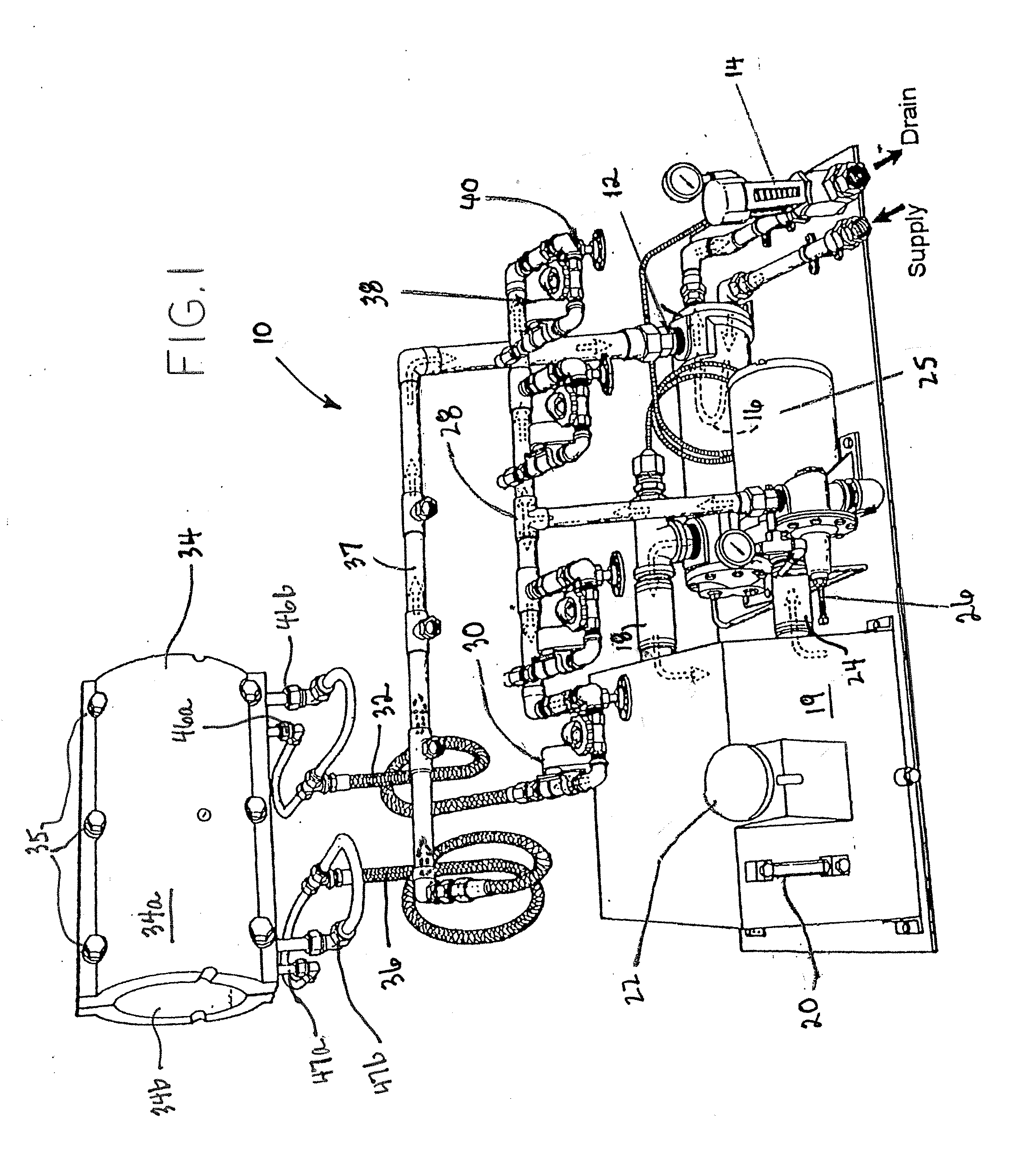
[0016]Referring to FIG. 1, there is shown a schematic diagram of a zone water heating / cooling system 10 for use with a conventional extruder system in which the inventive coolant is intended for use. Water heating / cooling system 10 is adapted to receive water from a conventional water supply. The incoming water is provided to a heat exchanger 12. Also provided to heat exchanger 12 is the coolant of the present invention which is circulated in the heater / cooler portion 34 of the extruder system. Heat exchanger 12 includes a coil 16 shown in dotted line form. In heat exchanger 12, water from the water supply is used to control the temperature of the coolant circulated through a heater / cooler 34 which forms a portion of a conventional high temperature extrusion system, with the remaining portions of the extrusion system not shown for simplicity. The water provided from the supply to the heat exchanger 12 is discharged to a drain via a regulating valve 14 for controlling the temperature...


PUM

PropertyMeasurementUnit
Fractionaaaaaaaaaa
Fractionaaaaaaaaaa
Temperatureaaaaaaaaaa

Abstract

Water-cooled extrusion equipment capable of operating at high temperatures in forming chemical and plastic components is highly subject to water-influenced corrosion of, and/or deposition of water-borne dissolved solids on, the narrow conduits carrying the circulating coolant and the system components and auxiliaries in contact with the coolant. The inventive water-based coolant circulated through the extrusion equipment's cooling passages is purified, thus having a reduced amount of dissolved solids and incorporates: (1) a yellow metal inhibitor for preventing corrosion and fouling of non-ferrous metals forming the coolant-bearing passages; (2) an organic/inorganic alkaline nitrogen-based compound to raise the pH of the water and reduce corrosion; and (3) a reducing agent to passivate the equipment's steel surfaces to reduce metal loss. The use of the inventive coolant increases reliability and operating lifetime of the extrusion equipment, while reducing equipment downtime and associated costs without modification to existing systems.

Description

FIELD OF THE INVENTION[0001]This invention relates generally to water-cooled extrusion equipment, and is particularly directed to an improved composition of the water used for cooling the extrusion equipment which reduces corrosion of, and the deposition of scale on, the water passages and system components and auxiliaries of the extrusion equipment to increase equipment reliability and prolong its operating lifetime, without changing the design or the composition of the equipment.BACKGROUND OF THE INVENTION[0002]During the operation of water-cooled extrusion equipment, severe system corrosion, mineral scale deposition and fouling can and often does occur in the cooling water passages. Various contributing factors to these potential operation interrupting conditions include, but are not limited to, high surface and bulk water temperatures, narrow water passages, the coupling / connection of components comprised of dissimilar metals, the use of high purity, unbuffered corrosive waters ...

Claims


Application Information

Patent Timeline
IPC IPC(8): C09K5/04
CPCC09K5/04C09K5/10C23F11/08C23F11/10C23F14/02
Inventor GREENLIMB, PETER, E.
Owner CHEMAGINEERING
Why Eureka
Try Eureka