Bi-metal assembling method and bi-metal assembled structure

a technology of assembling method and assembly method, which is applied in the field of assembling method and bimetal assembled structure, can solve the problems of affecting the quality of metal assemblage, so as to reduce the time for polishing, reduce the surface shrinkage and the generation of blowholes

Pending Publication Date: 2021-10-07
JU TENG INT HLDG
View PDF3 Cites 2 Cited by
  • Summary
  • Abstract
  • Description
  • Claims
  • Application Information

AI Technical Summary

Benefits of technology

[0024]In the present invention, the inner wall of the structure of the aluminum metal piece can be subject to CNC high-gross treatment. The two metals can be combined with smooth surface, and the smooth surface can reduce the time for polishing, the surface shrinkage and the generation of blowholes. Besides, the invention also uses plastic, surface with nano-structure or directly assembling two metals to achieve the assembling of the two metals to form bi-metal assembling structure.

Problems solved by technology

The casing / shell may be damaged, the cover paint of the casing / shell may be worn out and the protection layer may be broken due to collision or rub.
The metallic object on casing / shell of the electronic devices may be rust-eaten such that it cannot provide protection function and is not appealing for consumer for appearance.
However, the magnesium in the magnesium alloy has high activity to render difficulty to the surface plating process.
Therefore, the surface of the magnesium alloy is passivated to reduce activity and the process thereof is complicated.

Method used


Image

  • Bi-metal assembling method and bi-metal assembled structure
  • Bi-metal assembling method and bi-metal assembled structure
  • Bi-metal assembling method and bi-metal assembled structure

Examples


first embodiment

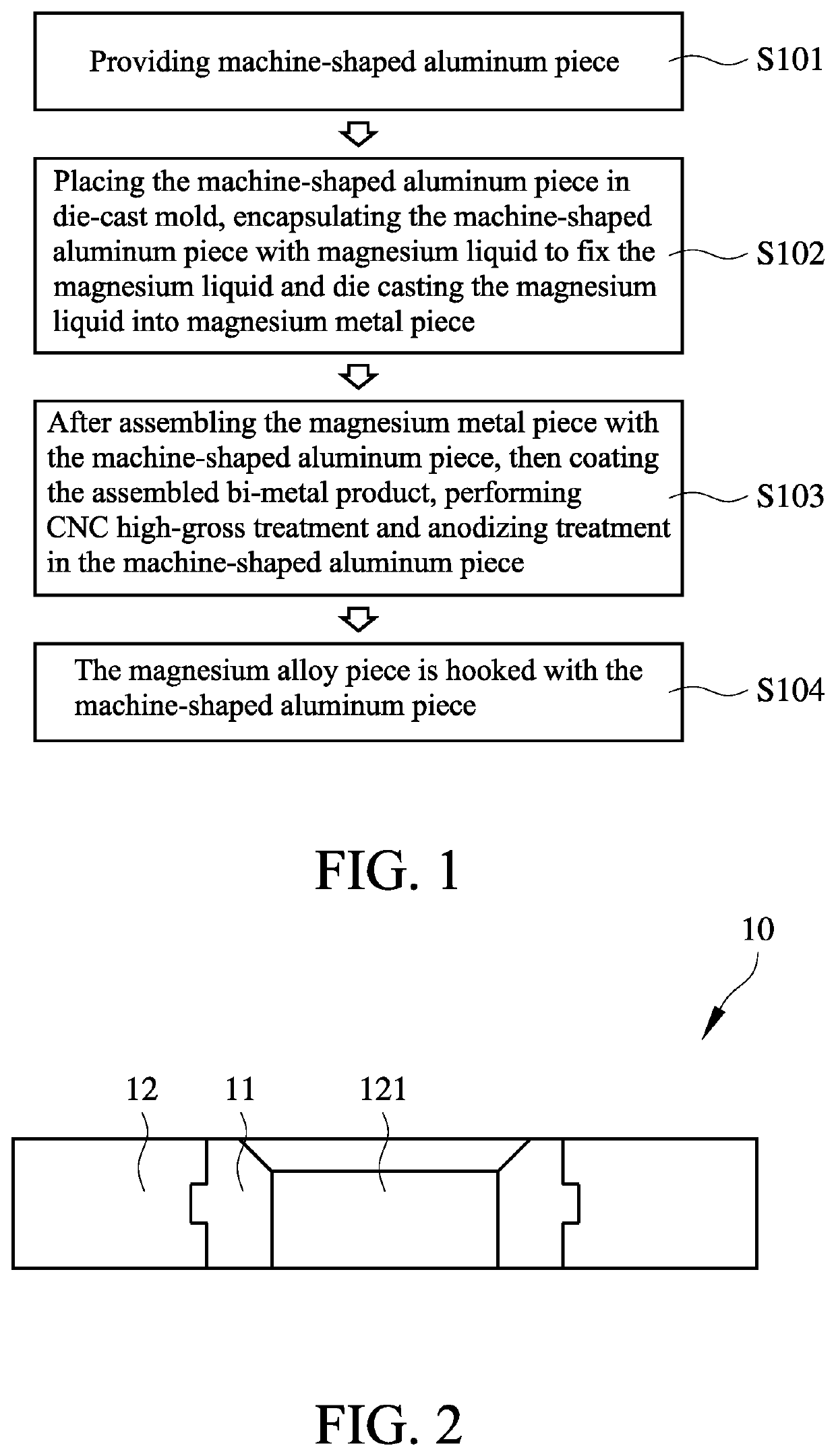
[0041]FIG. 1 shows the flowchart of the bi-metal assembling method according to the present invention. The method includes providing a machine-shaped aluminum piece (S101). The aluminum piece is placed in die-cast mold, encapsulated by magnesium liquid to fix the machine-shaped aluminum piece, and then die cast is performed such that the magnesium liquid forms a magnesium metal piece (S102). After the bi-metal product (the magnesium metal piece assembled with the machine-shaped aluminum piece) is finished, the bi-metal product is coated for protection. Then the machine-shaped aluminum piece is further processed to form a structure (the structure is aperture or suitable for high gross treated), and then subject to CNC high-gross treatment and anodizing treatment (S103). The coating can be achieved by lacquer coating or oxide layer coating. The magnesium alloy piece is hooked with the machine-shaped aluminum piece (S104). The smooth surface can reduce the time for polishing, the surfa...

second embodiment

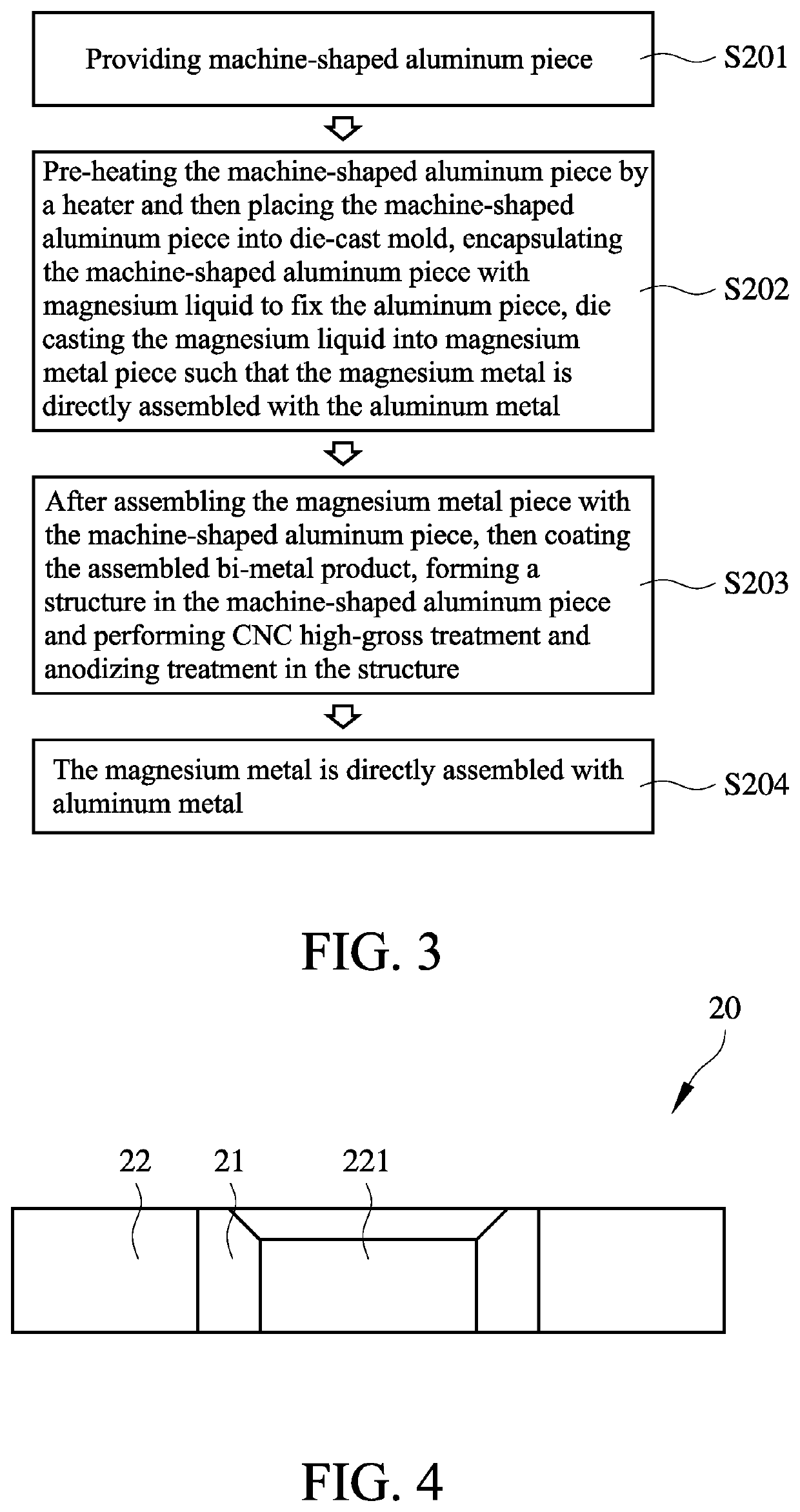
[0047]FIG. 3 shows the flowchart of the bi-metal assembling method according to the present invention. The method includes providing a machine-shaped aluminum piece (S201). The machine-shaped aluminum piece is pre-heated by a heater and then placed into die-cast mold, encapsulated by magnesium liquid to fix the aluminum piece, and then die cast is performed such that the magnesium liquid forms a magnesium metal piece, the magnesium metal piece is directly assembled with the aluminum piece (S202). After the bi-metal product (the magnesium metal piece assembled with the machine-shaped aluminum piece) is finished, the bi-metal product is coated for protection. Then the machine-shaped aluminum piece is formed with a structure therein and the structure is subject to CNC high-gross treatment and anodizing treatment (S203). The coating can be achieved by lacquer coating or oxide layer coating. The magnesium alloy piece is directly assembled with the machine-shaped aluminum piece (S204). Th...

third embodiment

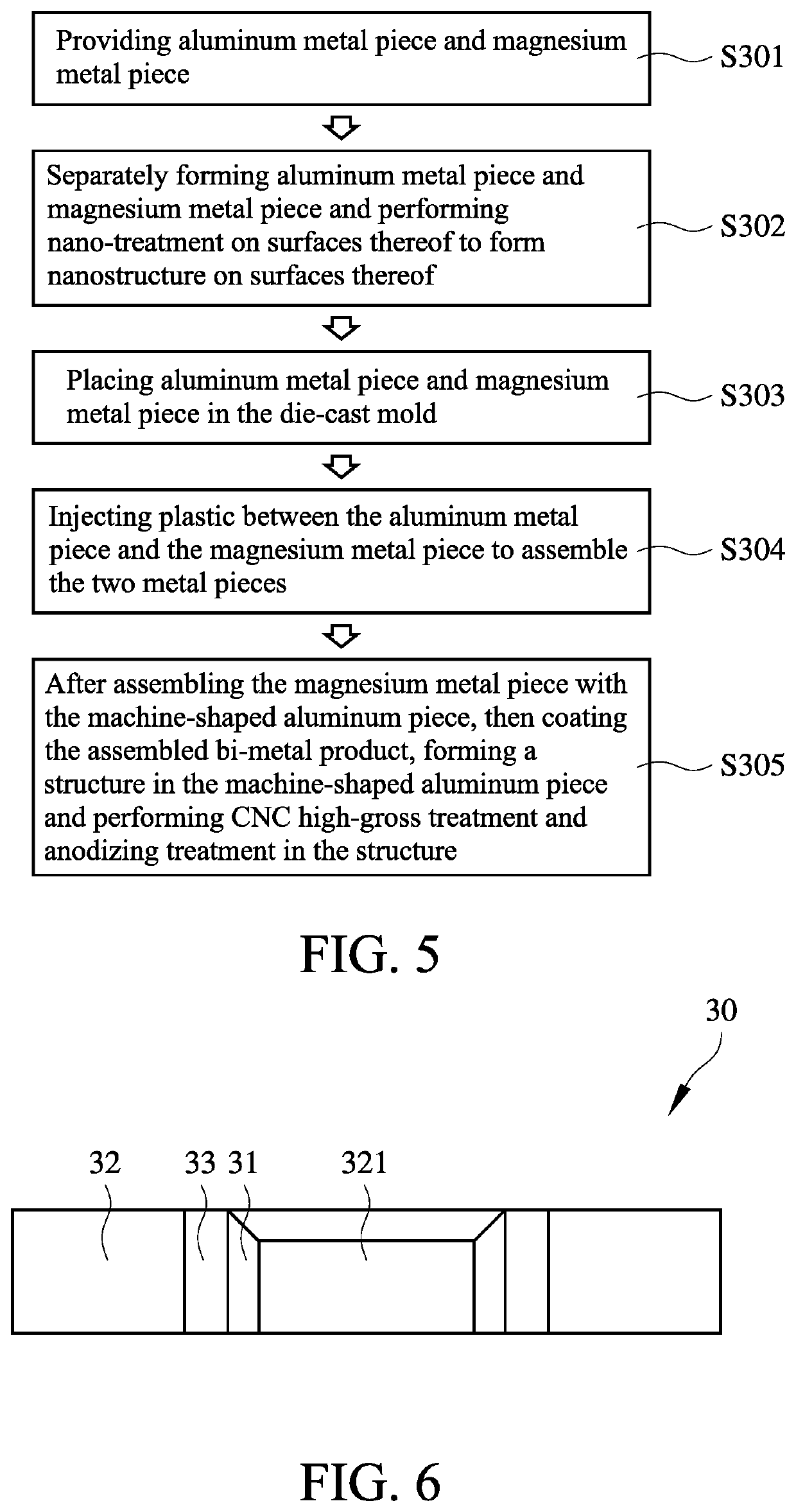
[0054]FIG. 5 shows the flowchart of the bi-metal assembling method according to the present invention. The method includes providing an aluminum metal piece and a magnesium metal piece (S301). The aluminum metal piece and the magnesium metal piece are separately formed and are subject to nano-treatment on surfaces thereof to form nanostructure on surface thereof (S302). The aluminum metal piece and the magnesium metal piece are placed in the die-cast mold at the same time (S303). Plastic is injected between the aluminum metal piece and the magnesium metal piece to form medium therebetween to assemble the two metal pieces (S304). After the bi-metal product (the magnesium metal piece assembled with the machine-shaped aluminum piece) is finished, the bi-metal product is coated for protection. Then the machine-shaped aluminum piece is formed with a structure therein and the structure is subject to CNC high-gross treatment and anodizing treatment (S305). The coating can be achieved by la...


PUM

PropertyMeasurementUnit
temperatureaaaaaaaaaa
microstructureaaaaaaaaaa

Abstract

The present invention provides a bi-metal assembling method. The method provides a machine-shaped aluminum piece and places the machine-shaped aluminum piece into a die-cast mold. The machine-shaped aluminum piece is encapsulated with a magnesium metal liquid and die cast is performed. The assembled bi-metal structure is coated for protection and CNC high-gross treatment and anodizing treatment is performed in the machine-shaped aluminum piece. The magnesium alloy piece is hooked with the machine-shaped aluminum piece for assembling. The bi-metal structure has smooth surface to reduce the time for polishing, surface shrinkage and generation of blowholes. The present invention also provides a bi-metal assembled structure.

Description

BACKGROUND OF THE INVENTION1. Technical Field[0001]The present invention relates to a bi-metal assembling method and a bi-metal assembled structure.2. Description of Prior Art[0002]The present invention relates to a bi-metal assembling method and a bi-metal assembled structure.[0003]The casing / shell of the electronic devices may include a plurality of structural elements. For example, the laptop computer may include display and main body. The display may include upper cover and display main body, while the main body may include keyboard cover and bottom structure. The above mentioned main body and keyboard cover may contain any suitable material.[0004]The casing / shell of the electronic devices, such as casing of portable electronic devices, may be in frequent contact with other objects such as table, user hand, ground, magnesium alloy object such that the casing / shell of the electronic devices may have deformation. The casing / shell may be damaged, the cover paint of the casing / shell...

Claims


Application Information

Patent Timeline
Patent Type & Authority Applications(United States)
IPC IPC(8): B22D19/16B29C45/00B23P15/24B23H5/04B22D21/04B23P15/00C25D11/04
CPCB22D19/16B29C45/0055B23P15/24B29L2031/34B22D21/04B23P15/007C25D11/04B23H5/04B22D17/22C22F1/04B23P15/00B23P11/00C25D11/30
Inventor WANG, HSIANG-JUIYANG, SHUN-JIEHSIAO, CHENG-PING
Owner JU TENG INT HLDG
Why Eureka
Try Eureka